
![spare parts catalog CLAAS Parts Doc Offline Update v933 [05.2026]](/imgs/type_zapch.gif)
The Claas parts catalog 05/2026 Upd 933 features step-by-step service procedures, repair illustrations, detailed wiring diagrams, and manufacturer specifications and are easy to follow.
200$
[05/2026]
| |
| Type of catalogue: | repair manual |
| Make: | Peterbilt |
| Region: | WorldWide |
| Inclusive languages: |
English |
| Amount of disks: |
PDF file, 67 pages |
| OS: | Windows XP 32 bit, Windows 7 32 bit, Windows 7 64 bit, Windows 8/8.1 32 bit, Windows 8/8.1 64 bit, Windows 10 32 bit, Windows 10 64 bit, Windows 11 64 bit, Windows 11 Pro 64 bit |
| Price, USD: | 49 |
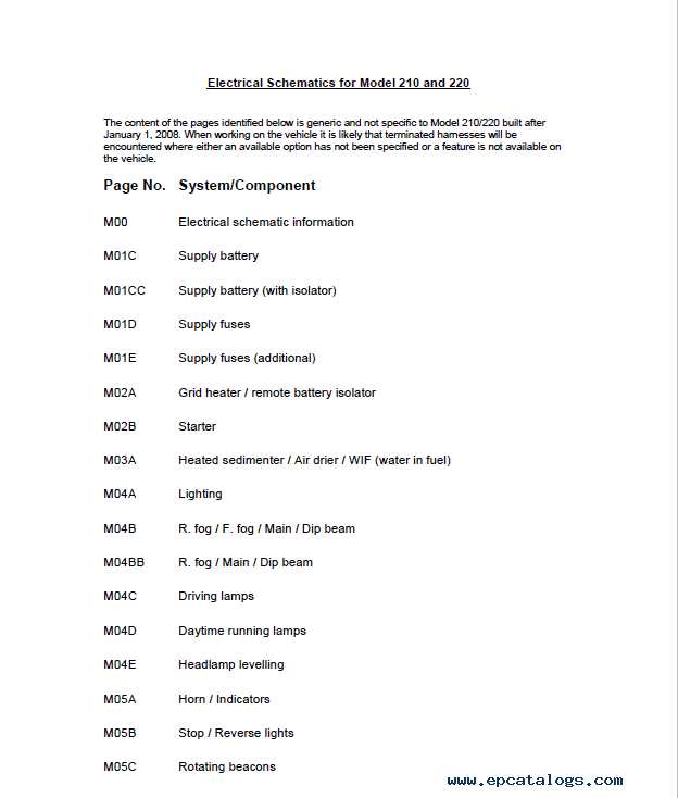
This manual covers the electrical wiring schematics for Peterbilt 210 and 220 trucks, focusing on 2007–2008 compliant models. It is a practical reference used when diagnosing electrical faults, tracing circuits, or working with cab-to-chassis interfaces.
Inside, you’ll find clearly structured diagrams for key systems such as lighting, ABS, battery supply, fuse distribution, CAN communication lines, and auxiliary components. The manual also includes connector pinouts with detailed functions, which makes it easier to understand how different systems are linked together.
Rather than being tied to a single configuration, the schematics are designed to be generic. This means you may encounter unused connectors or optional circuits depending on the truck’s equipment level—something that’s normal when working with real vehicles. :contentReference[oaicite:0]{index=0}
This is the kind of document you keep open while working: whether you're tracking down a lighting issue, verifying a sensor signal, or checking power supply paths, it helps you move step by step without guessing.
Electrical issues on modern trucks rarely come down to a single broken wire. More often, it’s about understanding how systems interact—where power comes from, how signals travel, and which components sit in between. That’s exactly where this manual becomes useful.
The schematics are laid out by system, so you can focus only on what you need. For example, if you're dealing with lighting, you’ll see how headlamps, fog lights, and indicators are wired, including fuse protection and switch logic. If the problem is deeper—like ABS or CAN communication—you can follow the signal path across connectors and control units.
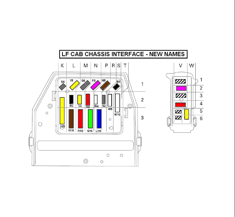
One of the most helpful parts of the manual is the connector breakdown. Each connector is listed with pin numbers, functions, and references to schematic pages. This makes it much easier to test circuits in real conditions, especially when working directly at the cab-chassis interface.
The document also explains wiring conventions—such as cable sizes, color coding, and CAN bus structure—so even if you’re not familiar with this specific model, you can quickly get oriented. :contentReference[oaicite:1]{index=1}
In practice, this manual is useful for:
It’s a straightforward technical document—no filler, just the information you actually need when something doesn’t work as expected.
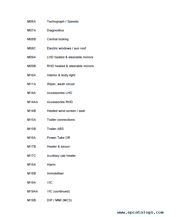
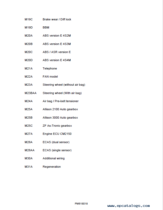
The manual is structured by system codes, making it easy to navigate directly to the part of the truck you’re working on. Each section focuses on a specific component or electrical system.
This structure helps you jump straight to the relevant system without scanning the entire manual, which is especially useful during diagnostics or repairs.
The manual is delivered as a digital PDF file available for instant download immediately after purchase.
This format is especially convenient when you need quick access during diagnostics or repairs.
Our company provides for sale original spare part catalogs, workshop manuals, diagnostic software for all models of engines, cars, trucks, buses, forklifts, tractors, harvesters, cranes, buldozers, generators, construction and agricultural machines, motorcycles. To purchase a catalog online, please add the product to your cart, fill in the contact form online. Our managers proceed your order the same day.

Paccar Peterbilt 579 Model 2012 HVAC Service Manual PDF
Electronic guide covers helpful and important illustrations, diagrams, and schemes which will be additional material for your equipment.
49$
[2012]
|
Peterbilt CAT 3126E Model Schematic Manual PDF
Download the Peterbilt CAT 3126E Wiring Schematic Manual in PDF format. This 2-page guide provides clear electrical schematics for easy troubleshooting and repairs.
39$
[2020]
|
Peterbilt Ultrasleeper Schematic Manual PDF
This Manual contains detailed electrical wiring Ultrasleeper Schematic information with descriptions, notes.
30$
[2020]
|
Peterbilt Model 362 Cab Wiring Schematic Manual PDF
Electronic guide contains several pages when you can see operation information, control material, detailed diagrams of all components and parts for this Peterbilt Cab Model.
49$
[2020]
|

© 2026 epcatalogs.com Peterbilt 210 & 220 Electrical Wiring Schematics Manual PDF 2007-2008, Trucks / Buses Repair, repair manual |
Terms of Service | DMCA Notice Of Copyright Infringement |


|