
![spare parts catalog CLAAS Parts Doc Offline Update v951 [10.2026]](/imgs/type_zapch.gif)
The Claas parts catalog 10/2026 Upd v951 features step-by-step service procedures, repair illustrations, detailed wiring diagrams, and manufacturer specifications and are easy to follow.
200$
[10/2026]

| |
| Type of catalogue: | repair manual |
| Make: | New Holland |
| Region: | WorldWide |
| Inclusive languages: |
English |
| Amount of disks: |
1 CD, 1 PDF, 646 pages |
| Availibility | Instant Download |
| OS: | Windows XP 32 bit, Windows 7 32 bit, Windows 7 64 bit, Windows 8/8.1 32 bit, Windows 8/8.1 64 bit, Windows 10 32 bit, Windows 10 64 bit, Windows 11 64 bit, Windows 11 Pro 64 bit |
| Price, USD: | 59 |
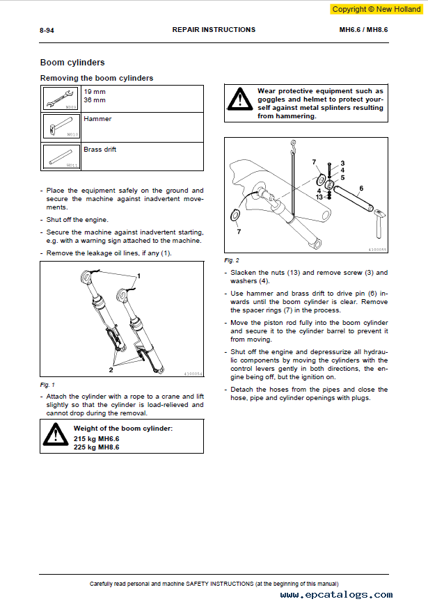
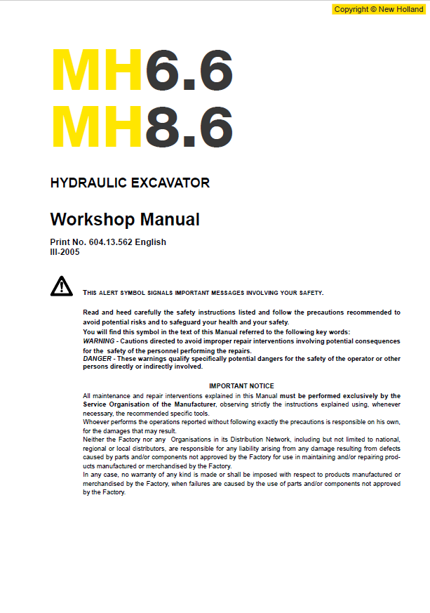
This workshop manual covers the New Holland MH6.6 and MH8.6 hydraulic excavators. It explains how the machine’s systems work and provides service specifications and step-by-step repair procedures, supported by illustrations and circuit diagrams.
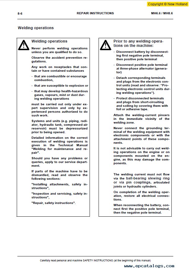
The procedures are intended for qualified service personnel. Follow the manufacturer’s instructions and use the specified special tools where required.
Alongside service specifications and recommended maintenance materials, the manual provides adjustment and replacement information. It identifies the special tools used for cylinder work and for servicing axles and gearboxes.
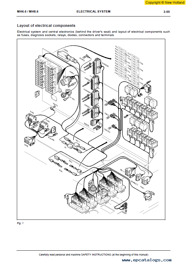
The electrical and electronic sections explain the machine’s wiring and control systems, including the central electronic unit and electro-hydraulic pilot control. Circuit diagrams and component locations support fault tracing. The manual also covers CAN bus components, ESX coding and electronic load-limit regulation.
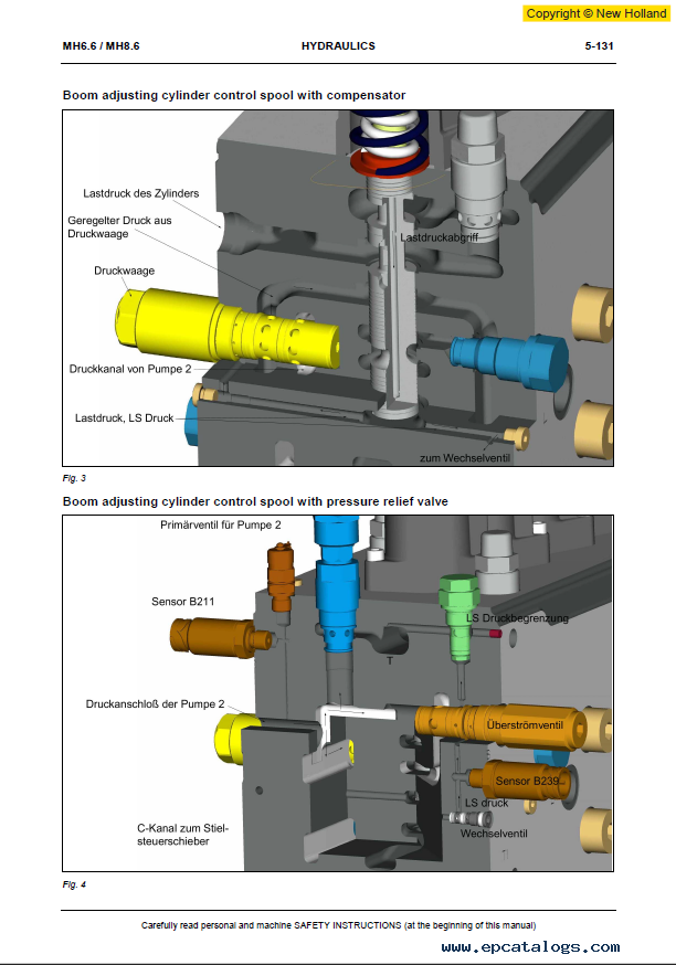
The hydraulic section follows power flow through the machine and explains individual circuits and combined functions. It includes attachment circuits for boom-adjusting and monoblock-boom equipment. Calibration and performance testing are also covered, along with troubleshooting and repair instructions.
Personal safety instructions
Safety instructions before starting work
Working from the operator’s seat only
Never take passengers on the machine
Safety instructions for machine operation
Taking care during operation
Distance from overhead power lines
Safety instructions for maintenance and servicing
Warning and instruction signs
Organizational measures
General service data
Foreword
Data sheet for MH6.6 cylinders
Data sheet for MH8.6 cylinders
Bucket-induced protrusion
SI and additional units
Conversion tables, Part 1
Conversion tables, Part 2
Calculation examples
Tightening torques
Special tools for cylinders
Special tools for axles and gearboxes
Spacers
Machine construction
Description of the machine with boom-adjusting equipment
Description of the machine with monoblock-boom equipment
Superstructure components: overview
Engine assembly components: overview
Hydraulic system components: overview
Drive unit components: overview
Undercarriage components: overview
Fundamentals
Automotive electrical systems
Cable harnesses
Fuses
Checking and replacing fuses
Table of fuses
Electrical circuit diagrams for supplementary functions
Layout of electrical components
Electrical system: central electronics behind the driver’s seat
Electrical system for electro-hydraulic pilot control
Electrical system for the pilot control unit, solenoid valves, sensors and switches
Electrical system in the engine compartment
Electrical system for the undercarriage control block
Electrical system for undercarriage stabilization
Electrical components by code number
Control
Introduction
Electronic control unit
Power supply
Components on CAN bus 1
Components on CAN bus 2
ESX coding
PCS: Power Control System
PCS components
Working, slewing and pilot-control circuits in the superstructure
Working, travel and pilot-control circuits in the undercarriage
Hydraulic circuit diagrams
Drive unit
Control block
Pilot-control system
Travel circuit of the 20 km/h version
Travel circuit of the 25/30 km/h version
Braking, steering and fan circuit
Undercarriage stabilizers
Boom cylinder circuit with regeneration circuit
Bucket cylinder circuit
Stick cylinder circuit with regeneration function
Adjusting cylinder circuit with pressure compensator and relief valve
Combined functions
Hydraulic hammer circuit: boom-adjusting equipment
Hammer circuit with auxiliary function: boom-adjusting equipment
Shears/crusher circuit: boom-adjusting equipment
Hydraulic hammer circuit: monoblock-boom equipment
Hammer circuit with auxiliary function: monoblock-boom equipment
Shears/crusher circuit: monoblock-boom equipment
Slewing system
Grab rotation mechanism
Before undertaking calibration work
Display, service and calibration
Repair instructions
General information
Superstructure components
Link between superstructure and undercarriage
Components
Undercarriage components
Equipment and components
Wear parts
Engine
After payment, the PDF manual is sent to the email address provided with your order, usually within 1–10 minutes. Please check that your email address is correct at checkout.
All pages of the PDF are printable. You can print the procedures you need for a particular job and keep them beside you in the workshop.
For questions about the manual or help with your order, contact our support team. After-sales support is available.
Our company provides for sale original spare part catalogs, workshop manuals, diagnostic software for all models of engines, cars, trucks, buses, forklifts, tractors, harvesters, cranes, buldozers, generators, construction and agricultural machines, motorcycles. To purchase a catalog online, please add the product to your cart, fill in the contact form online. Our managers proceed your order the same day.
![Diagnostic Software New Holland Electronic Service Tool CNH EST 9.15 [2026] Engineering Diagnostic Software](/imgs/diagnostics_icon.gif)
New Holland Electronic Service Tool CNH EST 9.15 [2026] Engineering Diagnostic Software![Diagnostic Software New Holland Electronic Service Tool CNH EST 9.15 [2026] Engineering Diagnostic Software](https://www.epcatalogs.com/file/base/7wA2eiQzaw96Mud+nQLe62FMZmZxTTk819fwjKwFzn9gZlueS7pErMi5cA5I4B9rnJjvyM2KHVeYq8dAqLFqg6eVylUigwGA14M6GWQO8C:2FaqSq5rLX38HGZjM8wALuylflj8yTHY6HQGzotXlCesqQ76kvVlAw5/case-new-holland-electronic-service-tools-cnh-est-software-download.webp)
The dealer software Electronic Service Tools CNH EST 9.15 update 0 (ex v9.3, v9.4, v9.5, 9.6, 9.7) with the highest engineering access Level available for download or shipping worldwide with online support!
250$
[10/2026]
|
CNH Display Codes for the Paid Features 2023 v1.1
The app generates codes for CNH displays to unlock paid features. Codes are entered through the display
3999$
[2024]
|
CNH Approval Password Generator 2023 NBV2
CNH (Case/New Holland) Generate approval passwords for Blank ECU, ECU Reassignment, and Download Crash Recovery; Supported ECU types: EDCMS62, EDC7, CNHEDC7UC31, EDC16C39.
1199$
[11/2024]
|
CNH Firmware Decrypt Encrypt Tool (FEDT) v2022.22
CNH Firmware Encrypt & Decrypt tool 2022.22 is Windows desktop software that supports decryption and encryption for *.enc and *.cre files from CNH.
999$
[12/2023]
|


© 2026 epcatalogs.com New Holland Hydraulic Excavator MH6.6, MH8.6 Workshop Manual PDF, Heavy Technics + Repair, repair manual |
Terms of Service | DMCA Notice Of Copyright Infringement |


|