

The Claas parts catalog 10/2026 Upd v951 features step-by-step service procedures, repair illustrations, detailed wiring diagrams, and manufacturer specifications and are easy to follow.
200$
[10/2026]

| |
| Type of catalogue: | repair manual |
| Make: | Case |
| Region: | WorldWide |
| Inclusive languages: |
English |
| Amount of disks: |
1 CD, 1 PDF, 1214 pages |
| Availibility | Instant Download |
| OS: | Windows XP 32 bit, Windows 7 32 bit, Windows 7 64 bit, Windows 8/8.1 32 bit, Windows 8/8.1 64 bit, Windows 10 32 bit, Windows 10 64 bit, Windows 11 64 bit, Windows 11 Pro 64 bit |
| Price, USD: | 59 |
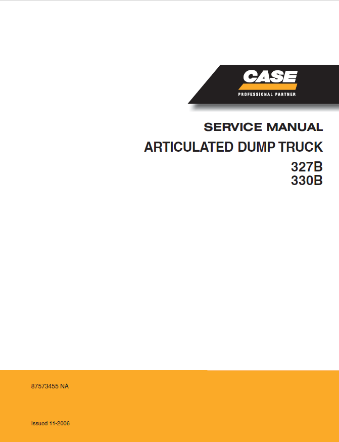
This service manual covers the Case 327B and 330 articulated dump trucks. It provides detailed technical information on machine systems, operating principles, maintenance requirements, troubleshooting, service specifications, and step-by-step repair procedures, supported by diagrams, illustrations, and technical data.
The procedures are intended for qualified service personnel. Follow the manufacturer's safety instructions, use the specified tools, and observe the recommended tightening torques and adjustment specifications when servicing the machine.
Service and Repair Coverage
The manual covers scheduled maintenance, general operating procedures, technical specifications, identification data, fluid capacities, tire pressures, tightening torques, and diagnostic fault codes. It includes engine service procedures for the electronic fuel injection system, variable geometry turbocharger, cooling and lubrication systems, and engine disassembly, inspection, repair, and reassembly.
The drivetrain sections provide detailed service information for the automatic transmission, torque converter, clutches, retarder, central differential lock, front axle, intermediate axle, rear axle, and driveline. Procedures include oil changes, component removal and installation, gear and bearing adjustments, differential overhauls, planetary reduction gear repairs, and brake servicing.
The hydraulic and suspension sections cover the steering and dumping systems, emergency steering, braking hydraulics, suspension cylinders, hydro-pneumatic suspension elements, and hydraulic pumps and valves. Testing procedures, pressure specifications, adjustment instructions, and component overhaul procedures support accurate diagnosis and repair.
The electrical section explains the multiplex control system, CAN communication networks, engine and transmission electronic control units, sensors, actuators, wiring harnesses, connectors, relays, fuses, and diagnostic procedures. Additional coverage includes the pneumatic system, manual and automatic greasing systems, air conditioning, cab and engine hood tilting mechanisms, and chassis components.
The manual also provides procedures for servicing the articulation joint, checking and correcting chassis deformation, removing and reinstalling the dump body, and inspecting major structural components. Technical diagrams, component locations, wiring schematics, and system layouts help technicians identify faults and carry out maintenance and repair work.
CONDITIONS OF USE AND SAFETY INSTRUCTIONS
CONDITIONS OF USE
INFORMATION ON THIS HANDBOOK
Definitions
Contents
Symbols
Purpose of this handbook
To whom this handbook is addressed
Safekeeping of this handbook
Updates to this handbook
Units of measure
SCHEDULED USE
VEHICLE DRIVERS
WASTE DISPOSAL
WARRANTY AND LIABILITY OF THE MANUFACTURER
Warranty conditions
Liability
SERVICE
After sales service
Spare parts
GENERAL OPERATION RULES
Pre-disassembly preparation
During disassembly
After disassembly
During assembly
Interchangeable parts
Welding on the chassis
SAFETY INSTRUCTIONS
INTRODUCTION
Safety information and symbols
General instructions
PREVENTING FIRES
ROLLOVER ACCIDENTS
Prevention
What to do if the vehicle rolls over
Structure of the cab
INSTRUCTIONS FOR USE
Cab
Starting and stopping
Driving the vehicle
Working the vehicle
Towing the vehicle
Replacing a wheel
MAINTENANCE
General
Power supply disconnection
Safety locks
Preventing injuries
Preventing intoxication and contamination
Preventing burns and electrocution
TECHNICAL DATA
VEHICLE COMPOSITION
DIMENSIONS (EMPTY VEHICLE)
DIMENSIONS WITH BODY RAISED
WEIGHTS
CENTER OF GRAVITY (HORIZONTAL POSITION)
PERFORMANCE
PERFORMANCE ALIGNMENT CHART
Using the alignment chart
Performance alignment chart
MAIN TECHNICAL SPECIFICATIONS
Chassis number
Case PIN plate
POSITION OF IDENTIFICATION DATA ON MAIN GROUPS
Cab
Chassis
Engine
Automatic transmission
Drive axles
Dumper cylinder (two)
Steering cylinder (two)
Suspension cylinders
MAIN TECHNICAL SPECIFICATIONS
Engine
Automatic transmission
Front drive axle
Intermediate and rear drive axles
Suspension
Brakes
Wheels and tires
Hydraulic system
Electrical system
Chassis
Drive cab
Body
LIST OF BULBS
CAPACITIES
TIRE PRESSURE TABLE
ANTIFREEZE CONCENTRATION IN ENGINE COOLANT
ANTIFREEZE CONCENTRATION IN WINDSCREEN WASHER FLUID
BATTERY ELECTROLYTE DENSITY TABLE
TIGHTENING TORQUE
PLATES APPLIED TO THE VEHICLE
Articulation joint left size
Cab access steps
EUROPEAN VERSION
INSIDE ENGINE HOOD PLATE
INSIDE CAB PLATE
U.S.A. VERSION
INSIDE ENGINE HOOD PLATE
INSIDE CAB PLATE
STANDARD TIGHTENING TORQUES
Screws and nuts with metric thread
MEASURES (INTERNATIONAL SYSTEM)
Force in N
Power in kW
Torque in Nm
Specific consumption in g/kWh
Pressure in kPa
Conversion values for British units
FAULT CODES
ENGINE FAULT CODES
FAULT CHECK USING THE DISPLAY
ENGINE FAULT CODES LIST
FAULT CHECK USING THE EDC WARNING LIGHT (BLINK-CODE)
ERROR CODES TABLE
AUTOMATIC TRANSMISSION FAULT CODES
FAULT CHECK USING THE DISPLAY
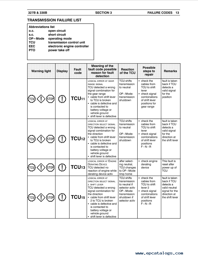
TRANSMISSION FAILURE LIST
DIAGNOSTIC CONNECTOR PIN-OUT
MULTIPLEX SYSTEM FAULT CODES
FAULT CHECK USING THE DISPLAY
MULTIPLEX SYSTEM FAULT CODES LIST
ENGINE
WALK AROUND
ELECTRONIC SYSTEM CONTROL
Electrical and electronic components
Component location on engine right–hand side
Component location on engine left–hand side
FUEL SUPPLY CIRCUIT
Pump–injector
Pumping element
Nozzle
Solenoid valve
Replacing pump–injectors
Injection phases
Filling phase
Injection phase
Pressure reduction phase
ENGINE AIR INTAKE SYSTEM
Top view
VARIABLE GEOMETRY TURBINE (VGT)
ACTUATOR ADJUSTMENT
Operating principle
VGT CONTROL SOLENOID VALVE
ENGINE EXHAUST SYSTEM
ENGINE EXHAUST SYSTEM
ENGINE BRAKE
COOLING
Water pump
Engine cooling system general diagram
Main circuit engine cooling circuit
Thermostat operation – engine cooling system
LUBRICATION
Lubrication system outline
Lubrication system outline – Detail A
Lubrication pump
Heat exchanger
Engine oil filter
TECHNICAL SPECIFICATION
GENERAL CHARACTERISTICS
ASSEMBLY CLEARANCE DATA
TIGHTENING TORQUES
TIGHTENING ORDER OF GEARBOX TO ENGINE BLOCK FASTENING SCREWS
Engine Support and Brackets
TOOLS
TROUBLESHOOTING BY SYMPTOMS
MAINTENANCE
Engine oil change
Engine oil filter change
Engine oil vapour filter change
Fuel circuit bleeding
Fuel filter change
Engine coolant fluid change and circuit check/cleaning
ENGINE REMOVAL–REPLACEMENT
Removal
Replacement
Checks and tests
REMOVAL–INSTALLATION OF THE FLEXIBLE COUPLING JOINT
Removal
Installation
RADIATOR GROUP REMOVAL–REPLACEMENT
Removal
Replacement
AUTOMATIC TRANSMISSION OIL–WATER HEAT EXCHANGER REMOVAL–REPLACEMENT
Removal
Replacement
DISMANTLING THE ENGINE ON THE BENCH
REPAIR OPERATIONS
Cylinder block
Checks and measurements
Cylinder lines
Replacing cylinder liners
Removal
Fitting and checking protrusion
CRANKSHAFT
Measuring main journals and crank pins
DETERMINATION OF PRELIMINARY DATA FOR SELECTION
Two series of numbers are marked on the front side of the block, in the position specified (top)
Choice of big end and main bearing half–shells
Definition of main journal and big end diameter class (journals with nominal diameter)
Replacing the pipeline control gear and the oil pump
Checking main journal installation clearance
Checking crankshaft end float
Piston–connecting rod assembly
Removal
Measuring the diameter of the pistons
Conditions for correct gudgeon pin–piston coupling
Piston rings
CONNECTING ROD
Bushings
Checking connecting rods
Mounting the connecting rod – piston assembly
Mounting the piston rings
Fitting the big end bearing shells
Fitting connecting rod – piston assemblies in the cylinder liners
Checking piston protrusion
Checking crankpin assembly clearance
CYLINDER HEAD
Dismounting the valves
Checking head bearing surface on cylinder block
Valves
Checking clearance between valve–stem and associated valve guide
Valve guides
Replacing injector cases
Checking protrusion of injectors
Timing distribution control
Drive cog pin
Drive cog
Pin double drive cog
Double drive cog
Bushing replacement
DISTRIBUTION
Checking cam lift and pin alignment
Camshaft
Bushes
Removal
Replacement
Valve springs
Fitting the valves and oil seal ring
ROCKER SHAFT
ROCKERS
ASSEMBLING THE ENGINE ON THE BENCH
Fitting the connecting rod – piston assembly into the cylinder liners
Fitting the cylinder head
Replacing flywheel casing
Replacing engine flywheel
Fitting pump–injectors
Replacing rocker shaft assembly
Timing of timing system shaft
Phonic wheel timing
Adjusting the unload/intake rockers play and pump injector control rockers preload
COMPLETING ENGINE ASSEMBLY
REPAIR WORKS
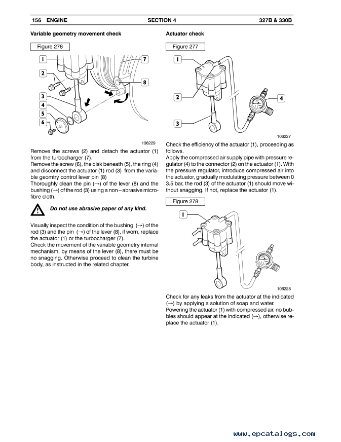
Variable geometry movement check
Actuator check
Check actuator excursion
Turbine body cleaning
POWER TAKE OFF DISTRIBUTION – P.T.O.
Tightening torques
Removal–reassembly of the power take–off
Removal
Reassembly
AUTOMATIC TRANSMISSION
DESCRIPTION
AUTOMATIC TRANSMISSION CROSS–SECTION VIEW
AUTOMATIC TRANSMISSION EXTERNAL PIPE ARRANGEMENT VIEW
TRANSMISSION SPEED SENSORS
• Speed sensor location
• Speed sensor setting
FUNDAMENTAL COMPONENTS
• Torque converter
• Lock–up clutch
• Clutches
• Hydrodynamic brake (retarder)
• Central differential lock
OPERATION
FRONT DIFFERENTIAL FITTING
OIL CIRCULATION SYSTEM – VERSION WITH RETARDER
OIL CIRCULATION SYSTEM – VERSION WITHOUT RETARDER
TRANSMISSION CONTROL SYSTEM COMPONENTS
• Key
• Connector key
TECHNICAL DATA
TIGHTENING TORQUE
EQUIPMENT
MAINTENANCE
• Oil level check
• Cold check
• Hot check
• Breather
• Oil change
• AEB procedure
• Display – meaning of AEB procedure messages
TRANSMISSION HYDRAULIC CONTROL DIAGRAM
• Position of the pressure and temperature measuring points
• Electro–hydraulic unit
REMOVAL–REPLACEMENT AUTOMATIC TRANSMISSION GEARBOX
• Removal
• Replacement
INSPECTION
• Preliminary operations
HYDRAULIC CONTROL UNIT
• Removal
• Refit
LOCK–UP CLUTCH VALVE (WK)
• Removal and disassembly
• Assembly and refit
GEARBOX AND GEAR DISASSEMBLY
• Converter and converter bell
• AN input shaft
• Lubricating pump
• Central splitter lock device
• Intermediate shaft
• Rear cover
• Central splitter
• Multiple–disk clutches
• Power takeoff shaft
• Transmitter disassembly
CLEANING, INSPECTING AND CHECKING
• Cleaning components
INSPECTING AND CHECKING
• Guards and machined surfaces
• Bearings and axial shims
• O–rings and seals
• Gears, grooves and threaded parts
• Rings and springs
• Clutch plates
• Roller bearings
• Shrink–fitting
GENERAL ASSEMBLY STANDARDS
• Lubricants used for assembly
• Clutches and pistons
• Lip seals
DISMANTLING AND REASSEMBLY OF MAIN UNITS
GEARBOX AND GEAR ASSEMBLY
FRONT AXLE
• DESCRIPTION
• First reduction: bevel pair
• Second reduction: hub and planitary train
• Brake pad
• SPECIFICATIONS AND DATA
• Hub
• Brake disc and caliper
• Bevel gear (first reduction)
• Planitary train and hub (second reduction)
• TIGHTENING TORQUES
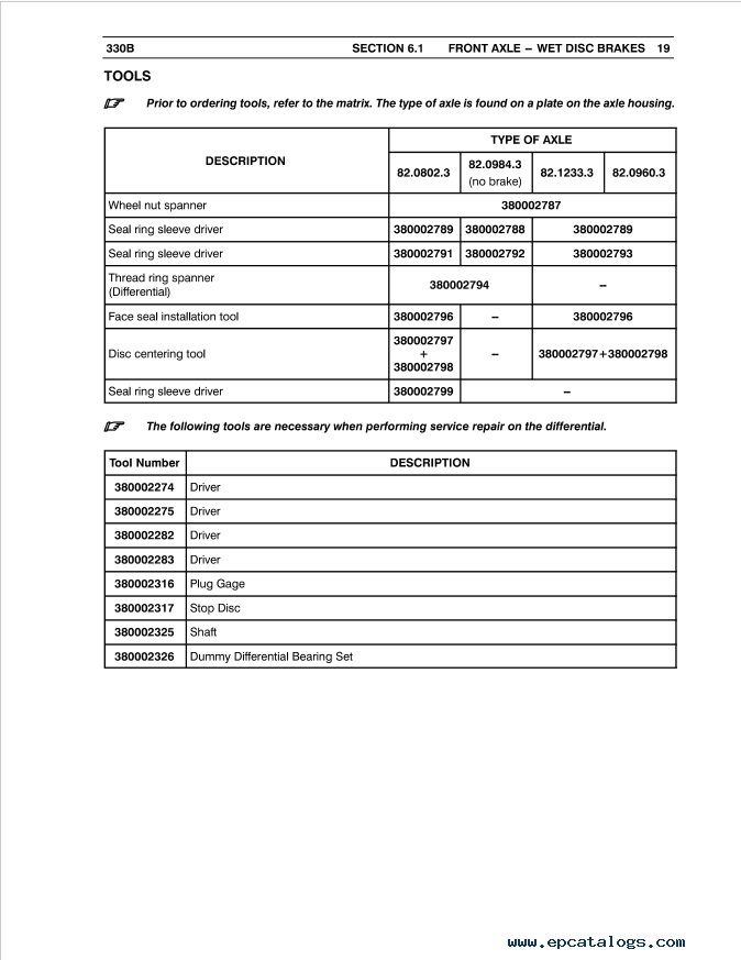
• EQUIPMENT
• DIAGNOSTICS
• Axle
• Brakes
• MAINTENANCE
• Replacement of the brake pads
• MAINTENANCE
• FRONT DIFFERENTIAL
• Checking oil level
• Changing the oil
• FRONT HUBS
• Checking oil level
• Changing the oil
• FRONT HUB REMOVAL–REFIT
• Removal
• BRAKE CALIPER DETACHMENT–REATTACHMENT
• Detachment
• Reattachment
• PLANITARY REDUCER OVERHAUL
• Disassembly
• Inspection of the dismantled parts
• Planitary reduction gear seals and thread–stops application and bearings scheme
• Planet–wheel holding plate assembly
• Hub
• Hub bearing preload determination
• Planet–wheel holding plate – fixed gear axial clearance determination
• Concluding operations
• FRONT DIFFERENTIAL OVERHAUL
• Disassembly
• Inspection of the disassembled parts
• Reassembly
• Diagram of bearings and the application of thread–locks and distributor and differential seals
• Diagram of the self–locking differential assembly
• BRAKE CALIPER OVERHAUL
• Disassembly
• Inspection of the disassembled parts
• Reassembly
• BRAKE DISC OVERHAUL
• Disassembly
• Reassembly
INTERMEDIATE AXLE
DESCRIPTION
Tandem transfer case
First reduction: bevel gear pair
Second reduction: hub and planetary train
Brake pad
SPECIFICATIONS AND DATA
Hub
Brake disc and caliper
Splitter unit and bevel gear pair (first reduction)
Hub and planetary gear (second reduction)
TIGHTENING TORQUES
TOOLS
DIAGNOSTICS
Axle
Brakes
MAINTENANCE
Replacement of the brake pads
Breaking-in of the pads
Checking oil level
Changing the oil
INTERMEDIATE AXLE REMOVAL–REFIT
Removal
BRAKE CALIPER DETACHMENT–REATTACHMENT
Detachment
Reattachment
PLANETARY REDUCER OVERHAUL
Disassembly
Inspection of the disassembled parts
Planetary reduction gear seals and thread-stops application and bearings scheme
Planet-wheel holding plate assembly
Brake unit and hub assembly
Hub bearing preload determination
Planet-wheel holding plate - fixed gear axial clearance determination
Concluding operations
TANDEM AXLE AND DIFFERENTIAL OVERHAUL
Disassembly
Inspection of the disassembled parts
Reassembly
Differential seals and thread-stops application and bearings scheme
Complete limited-slip differential assembly
Crown wheel and bearings assembly
Determination of the pinion axial position spacer (S1) thickness
Check of the pinion-crown wheel clearance
Verification of the pinion-crown wheel engagement impression area
Idle gear bearing preload determination
Pinion bearing preload determination
Idle gear and pinion assembly
Differential bearing preload determination
Coutershaft assembly
BRAKE CALIPER OVERHAUL
Disassembly
Inspection of the disassembled parts
Reassembly
BRAKE DISC OVERHAUL
Disassembly
Reassembly
REAR AXLE
• DESCRIPTION
• First reduction: bevel gear pair
• Second reduction: hub and planetary train
• Pinza freno
• SPECIFICATIONS AND DATA
• Hub
• Brake disc and caliper
• Bevel gear (first reduction)
• Hub and planetary gear (second reduction)
• TIGHTENING TORQUES
• EQUIPMENT
• DIAGNOSTICS
• Axle
• Brakes
• MAINTENANCE
• Replacement of the brake pads
• Breaking-in of the pads
• Checking oil level
• Changing the oil
• INTERMEDIATE AXLE REMOVAL–REFIT
• Removal
• BRAKE CALIPER REMOVAL–INSTALLATION
• Removal
• Installation
• PLANETARY REDUCER OVERHAUL
• Disassembly
• Inspection of the dismantled parts
• Planetary reduction gear seals and thread-stops application and bearings scheme
• Planet-wheel holding plate assembly
• Brake unit and hub assembly
• Hub bearing preload determination
• Planet-wheel holding plate – fixed gear axial clearance determination
• Concluding operations
• DIFFERENTIAL OVERHAUL
• Disassembly
• Inspection of the dismantled parts
• Reassembly
• Differential seals and thread-stops application and bearings scheme
• Complete limited-slip differential assembly
• Crown wheel and bearings assembly
• Thickness determination for bearing preload spacer S2 and bearing assembly
• Differential bearing preload determination
• Pinion assembly
• Check of the pinion-crown wheel clearance
• Verification of the pinion-crown wheel engagement impression area
DRIVELINE
DESCRIPTION
Central splitter
Distribution between the axles
Front axle
Intermediate and rear drive axles
Drive shafts
Driveline
Drive shaft
Central section
Parking brake unit
SPECIFICATIONS AND DATA
TIGHTENING TORQUES
INSPECTION PROCEDURES
Parking brake caliper release
Parking brake efficiency verification
MAINTENANCE
Replacement of the parking brake pads
REMOVAL – REPLACEMENT OF THE PARKING BRAKE DISC AND CALIPER
Detachment of disc
Detachment of the central section
Reattachment
CENTRAL BEARING OVERHAUL
Dismantling
Reassembly
SUSPENSIONS
DESCRIPTION
Front suspension
Hydro-pneumatic cylinder - description
Hydro-pneumatic cylinder - section
Hydro-pneumatic cylinder - view
Rear suspension
TIGHTENING TORQUES
Front suspension
Rear suspension
MAINTENANCE
Front suspension element inflating device
Equipment connection diagram
Checking suspension element height
Checking suspension element pressure
Inflating the suspension elements
Deflating the suspension element pressure
Changing the suspension fluid element
FRONT SUSPENSION REMOVAL-REPLACEMENT
Removal
Transfer shaft removal
Removal of the hubs
Replacement
FRONT SUSPENSION CYLINDER REMOVAL-REPLACEMENT
Removal
Replacement
REAR SUSPENSION REMOVAL-REPLACEMENT
Removal
Replacement
REMOVAL-REPLACEMENT OF THE REAR SUSPENSION STABILIZER BARS
Removal
REMOVAL-REPLACEMENT OF THE REAR SUSPENSION BUSHINGS
Elastic articulation bushing on the axles
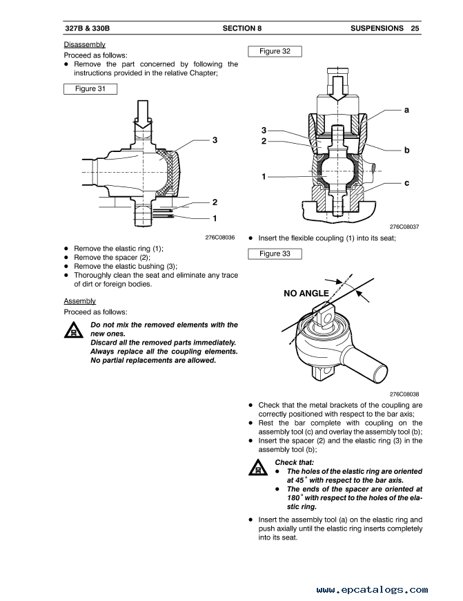
Flexible coupling
SUSPENSION CYLINDER OVERHAUL
Disassembly
Assembly
WHEELS AND TIRES
WHEELS
DESCRIPTION
SPECIFICATIONS AND DATA
TIGHTENING TORQUE
REPLACING A COMPLETE WHEEL
Disassembly
Fitting
TIRE–RIM DISASSEMBLY–ASSEMBLY
Disassembly
Cleaning of the wheel parts
Reassembly
HYDRAULIC SYSTEM
DESCRIPTION
General diagram
HYDRAULIC SYSTEM PRESSURE TEST POINTS
Vehicles with dry disc brakes
Hydraulic system pressures table – Vehicles with disc brakes
TECHNICAL DATA
Main pump
Brake pump
Emergency steering pump
Dumping distributor
Steering valve
Back–pressure valve
Accumulators
Fan drive
Cartridge filters
STEERING AND DUMPING SYSTEM
STEERING AND DUMPING SYSTEM – DESCRIPTION
Main components
Function
Main components of the steering–dumping system
HYDRAULIC DIAGRAM
Steering–dumping hydraulic system
Steering–dumping hydraulic diagram
OPERATION
TOPOGRAPHICAL DIAGRAMS
Forward chassis diagram
Rear chassis diagram
A OIL TANK (ONLY DISC BRAKE VERSION)
B STEERING/DUMPING DISTRIBUTOR
C MAIN FILTER – TIPPING AND EMERGENCY STEERING GROUP
D COUNTERBALANCE VALVE
E MAIN PUMP
F EMERGENCY STEERING PUMP
G POWER STEERING
H HEAT EXCHANGER
L DUMPING CYLINDER
M STEERING CYLINDER
N REAR CHASSIS CONNECTOR PLATE
MAINTENANCE
Checking fitting and pipe tightness
Changing the fluid
MAIN SYSTEM
Replacing pressurised filter
Cleaning the (suction) filter
STEERING–DUMPING SYSTEM TEST PROCEDURES
Prescribed pressure values
Dumping and steering valves
REMOVAL–REPLACEMENT OF THE EMERGENCY STEERING VALVE – MAIN FILTER
Removal
Replacement
DUMPING VALVE REMOVAL– REPLACEMENT
Removal
Replacement
Dumping valve removal–replacement
DUMPING CYLINDER REMOVAL– REPLACEMENT
Removal
Replacement
Dumping cylinder removal–replacement
STEERING VALVE REMOVAL– REPLACEMENT
Removal
Replacement
MAIN PUMP REMOVAL–REPLACEMENT
Removal
Replacement
STEERING CYLINDER REMOVAL–REPLACEMENT
Removal
Replacement
DUMPING CYLINDER OVERHAUL
Dismantling
Checking components
Assembly
Functional testing
STEERING CYLINDER OVERHAUL
Dismantling
Assembly
STEERING–DUMPING VALVE BLOCK OVERHAUL
Disassembly
Component position identification
Cleaning
Checks and inspections
Assembly
EMERGENCY STEERING SYSTEM
Main components
Function
Main component emergency steering system
Emergency steering hydraulic diagram
OPERATION
INSPECTION PROCEDURES
Check the efficiency of the emergency steering pump control
EMERGENCY STEERING PUMP REMOVAL–REPLACEMENT
Removal
Replacement
BRAKING SYSTEM
BRAKING SYSTEM
Main components
Function
Service and parking brakes – location
Braking system hydraulic diagram
OPERATION
TOPOGRAPHICAL DIAGRAMS
Forward chassis diagram
Rear chassis diagram
A BRAKE PUMP
C ACCUMULATORS
D FILTER AND LIMITATION VALVE
E BRAKE COMMAND VALVE
H REAR CHASSIS CONNECTOR PLATE
BRAKING SYSTEM TEST PROCEDURES
Pressure discharge
Pressure check
Pressure adjustment
Pedal position adjustment
MAINTENANCE
Braking hydraulic system air bleeding
Changing the fluid
Replacing pressurised filter
Cleaning the (suction) filter
BRAKE PUMP REMOVAL–REPLACEMENT
Removal
Replacement
HYDRAULIC ACCUMULATOR REMOVAL–REPLACEMENT
Removal
Replacement
RELAY VALVE REMOVAL–REPLACEMENT
Removal
Replacement
ELECTRICAL SYSTEM
• MULTIPLEX SYSTEM OVERVIEW
• Conventional control
• Multiplex system
• CAN LINE
• Static efficiency tests
• Measurement values
• MULTIPLEX SYSTEM GENERAL DIAGRAM
• TOPOGRAPHIC DIAGRAMS
• Chassis services wiring
• Engine wiring
• Automatic transmission wiring
• Cab wiring
• BULKHEAD CONNECTORS
• Bulkhead location
• Cab/engine wiring WHITE through bulkhead connector PIN OUT side
• Cab/services wiring BROWN through bulkhead connector PIN OUT side
• Cab/automatic transmission wiring YELLOW through bulkhead connector PIN OUT side
• DIAGNOSTIC CONNECTOR PIN-OUT
• CAN OPEN LINE
• CAN OPEN LINE block diagram
• CAN OPEN LINE circuit diagram
• BODY COMPUTER SYSTEM COMPONENTS
• CLUSTER
• CLUSTER location
• MIDAC 1 control unit PIN OUT
• HEAD
• HEAD and closing resistor location
• HEAD control unit PIN OUT
• HEAD control unit PIN OUT
• MIDAC
• MIDAC location
• Detachment and reattachment of the MIDAC connector
• MIDAC 1 control unit PIN-OUT
• MIDAC 2 control unit PIN-OUT
• LOCATION OF SENSORS AND ACTUATORS
• HEAD
• CAN J1939 LINE
• CAN J1939 line circuit diagram
• EDC ENGINE CONTROL UNIT
• EDC engine control unit PIN-OUT
• "A" Electro-injectors connector
• Color legend
• "B" chassis connector
• "C" sensors connector
• Color legend
• TRANSMISSION CONTROL UNIT (TCU)
• TCU identification plate
• Transmission control unit pin-out
• ELECTRICAL SUPPLY
• Batteries
• GROUND POINTS
• Interior control and utility arrangement
• Interior control and utility arrangement
• Indicators and warning lights
• Indicators and warning lights
• CLIMATE CONTROL SYSTEM
• Manual climate control
• Climate control system air vents
• RELAYS AND FUSES INTERCONNECTION CONTROL UNIT
• RELAYS AND FUSES
• Relays
• Supplementary relays
• Relays, resistors and diodes supplementary
• Fuse overview
• Supplementary fuses
• Fusebox component wiring
• VEHICLE DIAGNOSTIC CONTROL SYSTEM
• List of problems and interventions
• PROCEDURE
• ELECTRICAL SYSTEM
• Layout electrical system
PNEUMATIC SYSTEM
• DESCRIPTION
• Main Components
• PNEUMATIC DIAGRAM
• Pneumatic diagram
• COMPONENTS LOCATION PNEUMATIC SYSTEM
• TOOLS
• DIAGNOSTIC
• DRIER
• MAIN COMPONENTS PNEUMATIC SYSTEM
• COMPRESSOR
• SINGLE–CHBER AIR DRIER
• AIR INTAKE VALVE
• PRESSURE RELIEF VALVE
• PARKING BRAKE ENGAGING DISTRIBUTOR
• MANUAL CONDENSATION DISCHARGE VALVE
GREASE SYSTEM
MANUAL GREASING SYSTEM
AUTOMATIC GREASING SYSTEM
Location of the greasing points
AUTOMATIC GREASING SYSTEM CALIBTATION ADJUSTMENT
GREASING SYSTEM CALIBRATION
GREASING TIME ADJUSTMENT
Restoring grease dispenser functionality
Restore operation of the automatic greasing Control unit after disassembly/draining
CHECKS OF THE LUBRICATION CONTROL UNIT COMPONENTS
DISTRIBUTION DIVIDER
Description
Operation
Quantity of lubricant supplied
Indicators
AIR CONDITIONING SYSTEM
AIR–CONDITIONING SYSTEM
Functional principle
Functional outline
Component layout
Climate control system
Climate control system air vents
TECHNICAL DATA
EQUIPMENT
DIAGNOSTICS
Fan not working
Fan works but with poor air–flow
Normal function but poor air cooling
Compressor not functioning or functioning poorly
Diagnosis by pressure measurement
Low pressure circuit – insufficient pressure
Low pressure circuit – excessive pressure
High pressure circuit – insufficient pressure
High pressure circuit – excessive pressure
MAINTENANCE
System charge check
Cleaning/replacing passenger air cleaner
Cleaning condenser
GENERAL SERVICING
Usable fluids
Draining R134a fluid
Works on system piping
Compressor lubricant
ELECTRICAL SCHEMATIC
CAB
DESCRIPTION
ENGINE HOOD TIPPING HYDRAULIC SYSTEM
Component layout
Component layout
Operation
Diagram
CAB TIPPING HYDRAULIC SYSTEM
Cab tipping hydraulic system components location
Cab tipping hydraulic system diagram
Operation
CAB REMOVAL–REPLACEMENT
Removal
Replacement
CAB COMPONENTS REMOVAL–REPLACEMENT
ENGINE HOOD TIPPING CYLINDER
Detachment
Reattachment
CAB TILTING CYLINDER
Removal
Replacement
HOOD
Removal
Replacement
LOWER COVERS
Removal
Replacement
SIDE COVERS
Removal
Replacement
SIDE PANELS
Removal
Replacement
CHASSIS
DESCRIPTION
Front chassis
Rear chassis
Articulation joint
Interface flange
TIGHTENING TORQUES
ARTICULATION JOINT REMOVAL-REPLACEMENT
Removal
Dismantling
Articulation ball joint pre-load adjustment
Replacement
Reattachment
TESTS AND CHECKS
Chassis lateral bending check
Chassis lateral bending admitted
Finding chassis bending up and down
Vertical bending admitted
Finding chassis twist
Bending up and down admitted on chassis
REPAIR OPERATIONS
Precautions
Straightening the chassis
BODY DETACHMENT-REASSEMBLY
Detachment
Reassembly
Delivery (Instant Download)
After payment, the PDF manual is sent to the email address provided with your order, usually within 1–10 minutes. Please check that your email address is correct at checkout.
Printing and Support
All pages of the PDF are printable. You can print the procedures you need for a particular job and keep them beside you in the workshop.
For questions about the manual or help with your order, contact our support team. After-sales support is available.
Our company provides for sale original spare part catalogs, workshop manuals, diagnostic software for all models of engines, cars, trucks, buses, forklifts, tractors, harvesters, cranes, buldozers, generators, construction and agricultural machines, motorcycles. To purchase a catalog online, please add the product to your cart, fill in the contact form online. Our managers proceed your order the same day.

New Holland Electronic Service Tool CNH EST 9.15 [2026] Engineering Diagnostic Software
The dealer software Electronic Service Tools CNH EST 9.15 update 0 (ex v9.3, v9.4, v9.5, 9.6, 9.7) with the highest engineering access Level available for download or shipping worldwide with online support!
250$
[10/2026]
|
CNH Display Codes for the Paid Features 2023 v1.1
The app generates codes for CNH displays to unlock paid features. Codes are entered through the display
3999$
[2024]
|
CNH Approval Password Generator 2023 NBV2
CNH (Case/New Holland) Generate approval passwords for Blank ECU, ECU Reassignment, and Download Crash Recovery; Supported ECU types: EDCMS62, EDC7, CNHEDC7UC31, EDC16C39.
1199$
[11/2024]
|
CNH Firmware Decrypt Encrypt Tool (FEDT) v2022.22
CNH Firmware Encrypt & Decrypt tool 2022.22 is Windows desktop software that supports decryption and encryption for *.enc and *.cre files from CNH.
999$
[12/2023]
|


© 2026 epcatalogs.com Case ARTICULATED DUMP TRUCK 327B, 330 Service Manual PDF, Heavy Technics + Repair, repair manual |
Terms of Service | DMCA Notice Of Copyright Infringement |


|