

The Claas parts catalog 10/2026 Upd v951 features step-by-step service procedures, repair illustrations, detailed wiring diagrams, and manufacturer specifications and are easy to follow.
200$
[10/2026]

| |
| Type of catalogue: | repair manual |
| Make: | Case |
| Region: | WorldWide |
| Inclusive languages: |
English |
| Amount of disks: |
1 CD, 1 PDF, 384 pages |
| Availibility | Instant Download |
| OS: | Windows XP 32 bit, Windows 7 32 bit, Windows 7 64 bit, Windows 8/8.1 32 bit, Windows 8/8.1 64 bit, Windows 10 32 bit, Windows 10 64 bit, Windows 11 64 bit, Windows 11 Pro 64 bit |
| Price, USD: | 49 |
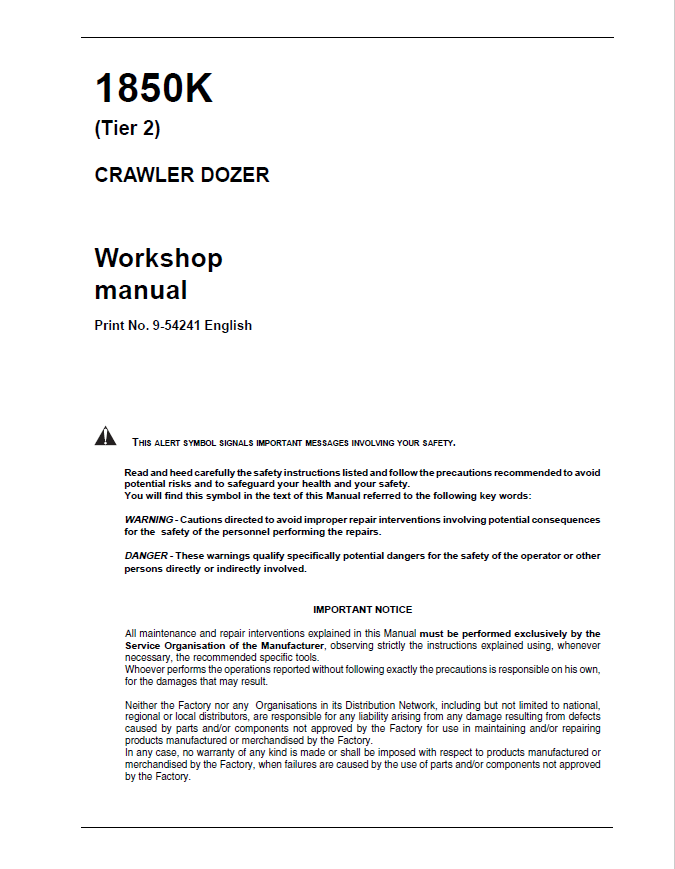
This workshop manual provides detailed service and repair information for the Case 1850K Tier 2 crawler dozer. It covers the engine, transmission, final drives, brakes, steering, undercarriage, hydraulic equipment and electrical systems, with technical diagrams, specifications, troubleshooting and step-by-step repair procedures.
Service and Repair Coverage
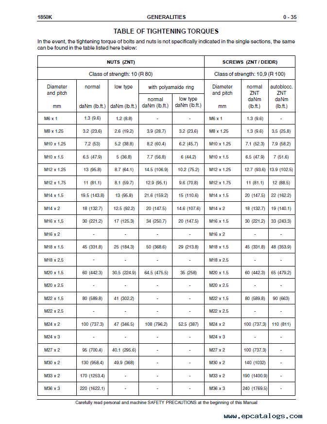
The manual includes machine specifications, identification data, dimensions, weights, tightening torques and technical information for LGP and LT/XLT configurations.
The engine section covers Series C engine specifications, mounting, diagrams and related components.
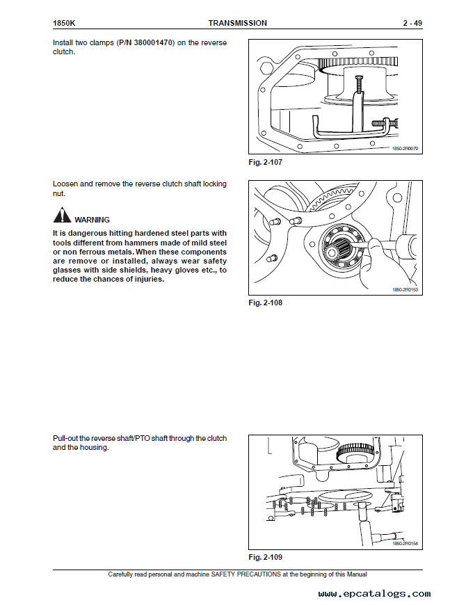
The transmission section includes torque converter and transmission operation, hydraulic circuits, pressure testing, troubleshooting, adjustments, removal, overhaul and reassembly.
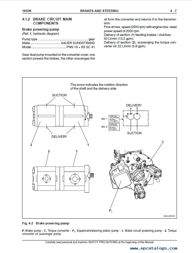
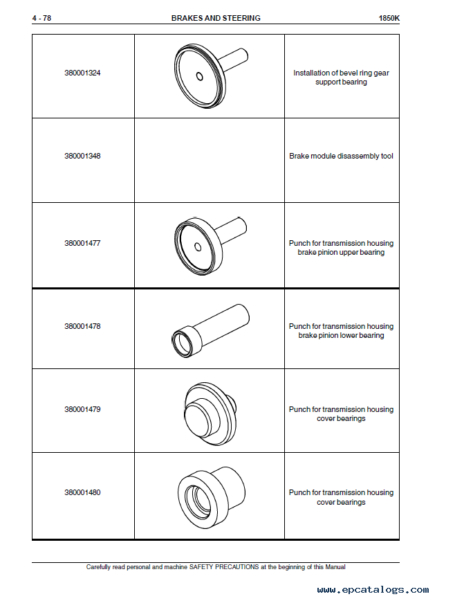
The final drive, brakes and steering sections provide component specifications, diagnostic procedures, pressure tests and detailed repair instructions.
The undercarriage section covers track chains, idlers, sprockets, rollers, track tensioners, inspection, wear limits and replacement procedures.
The hydraulic equipment section includes system diagrams, pump and control valve repairs, flow testing, blade installation and cylinder specifications.
The electrical section covers wiring diagrams, fuses, starting circuits, sensors, relays, instruments and diagnostic procedures.
The air conditioning section includes specifications, troubleshooting, error codes, refrigerant servicing and leak inspection.
This manual is a valuable technical reference for diagnosing problems, performing maintenance and completing mechanical, hydraulic and electrical repairs on the Case 1850K Tier 2 crawler dozer.
SECTION 0
GENERALITIES
TABLE OF CONTENTS
SUBJECT
SAFETY RULES
IDENTIFICATION DATA
Table of fluids used
Main dimensions
Technical data
1850K (LGP)
1850K (LT/XLT)
WEIGHT TABLE 1850K
LIST OF WEIGHTS FOR MAIN SERVICE COMPONENTS
STABILITY
GENERAL INSTRUCTIONS
TROUBLESHOOTING
UNITS OF MEASURE
TABLE OF TIGHTENING TORQUES
SECTION 1
ENGINE
TABLE OF CONTENTS
CHAPTER
SUBJECT
1.1 GENERAL SPECIFICATIONS
1.2 SERIES "C" ENGINE DATA
1.3 DIAGRAMS OF SERIES "C" ENGINE
1.4 MOUNTING OF ENGINE ON FRAME
1.5 AFTERCOOLER FAN DRIVE SYSTEM
1.6 THROTTLE LINKAGE
SECTION 2
TRANSMISSION
TABLE OF CONTENTS
CHAPTER
SUBJECT
2.1 GENERAL DESCRIPTION
2.1.1 Transmission torque converter hydraulic diagram
2.1.2 Transmission housing/propeller shaft/torque converter
2.2 TROUBLESHOOTING
2.3 TESTS
2.3.1 Torque converter stall test
2.3.2 Delivery pressure test procedure
2.3.3 Transmission gearshifting electric control valve
2.3.3.1 Positioning of diagnostic hoses
2.3.4 Transmission setting
2.4 PROCEDURES FOR THE REPAIR OF THE TORQUE CONVERTER
2.4.1 Removal
2.4.2 Re-Installation
2.4.3 Disassembly
2.4.4 Reassembly
2.5 PROCEDURES FOR THE REPAIR OF THE TRANSMISSION
2.5.1 Removal
2.5.2 Re-Installation
2.5.3 Disassembly
2.5.4 Overhaul of the forward speed clutch
2.5.5 Overhaul of the 3rd speed
2.5.6 Overhaul of the reverse speed clutch
2.5.7 Modulating valves (Disassembly/Assembly)
2.5.8 Pressure relief valve (Disassembly/Assembly)
2.6 SPECIFICATIONS AND DATA
2.6.1 General data
2.6.2 Tightening torques (Torque converter)
Transmission housing
2.6.3 Transmission Data
Transmission Clutch
Transmission clutch discs
1st - 2nd - 3rd speed Transmission Clutch modulating valves
Lube oil pressure relief valve
Forward/reverse modulating valves
Transmission pressure relief and torque converter safety valve
Torque converter/transmission feeding pump
Oil filters
2.7 SPECIAL TOOLS
SECTION 3
FINAL DRIVES
TABLE OF CONTENTS
CHAPTER
SUBJECT
3.1 GENERAL DESCRIPTION
3.1.1 Final drive (Exploded view and sectional view)
3.2 REPAIR PROCEDURES
3.2.1 Final drive (Removal/Disassembly)
3.2.2 Pulling the housing cover
3.2.3 Driving gear (Bearing removal)
3.2.4 Driving gear shaft (Bearing removal)
3.2.5 Description of installation of front seals (Long life)
3.2.6 Final drive (Assembly)
3.3 SPECIFICATIONS AND DATA
3.3.1 Final drive shaft and bearing fittings
3.4 SPECIAL TOOLS
SECTION 4
BRAKES AND STEERING
TABLE OF CONTENTS
CHAPTER
SUBJECT
4.1 GENERAL DESCRIPTION
4.1.1 Brakes hydraulic diagram
4.1.2 Brake circuit main components
Brake powering pump
Brake powering valve block
Brake pedal valve
Brake oil filter
4.1.3 Steering hydraulic circuit diagram
4.1.4 Steering circuit main components
Hydraulic motor
Steering piloting valve block
4.2 TROUBLESHOOTING
4.2.1 Diagnosis on the display
4.3 TESTS
4.3.1 Test of circuit pressures on diagnostics
4.3.2 Positioning of diagnostic hoses
4.3.3 Brake pedal adjustment
4.3.4 Test and setting of braking power valve block
4.4 REPAIR PROCEDURES
4.4.1 Brake pedal valve (removal/disassembly)
4.4.2 Brake power pump
4.4.3 Brakes and steering differential
Removal (preliminary operations)
Removal of the ring gear
Disassembly of the planet carrier assembly
Disassembly of the planet carrier differential assembly
Disassembly of the sun gear
Disassembly of the brake assembly
Re-assembly of the brake drum assembly
4.4.4 Check and inspection of brake packs
Re-assembly of the sun gear
Re-assembly of the planet carrier assembly
Re-assembly and re-installation of the ring gear assembly
Re-installation of brake/steering differential group into the transmission housing
SECTION 5
UNDERCARRIAGE
TABLE OF CONTENTS
CHAPTER
SUBJECT
5.1 GENERAL DESCRIPTION
5.1.1 Generalities
5.1.2 Main components
5.2 TROUBLESHOOTING
5.3 INSPECTIONS
5.3.1 Inspection and adjustment of track chains
5.3.2 Setting of the track tensioner pressure relief valve
5.4 REPAIR PROCEDURES
5.4.1 Track chain (Removal/Installation)
5.4.2 Replacing a damaged link and re-installation
5.4.3 Idler (Removal/Re-installation/Overhaul)
5.4.4 Track chain tensioner spring (Removal/Installation)
5.4.5 Track chain support rollers (Removal/Installation/Overhaul)
5.4.6 Track chain bottom rollers (Removal/Installation/Overhaul)
5.5 SPECIFICATIONS AND DATA
5.5.1 Idler
5.5.2 Sprockets
5.5.3 Track chains
5.5.4 Bottom rollers
5.5.5 Support rollers
5.5.6 Track tensioner device
5.5.7 Front cross-member pivots
5.5.8 Wear limits
5.6 SPECIAL TOOLS
SECTION 6
DOZING EQUIPMENT HYDRAULIC SYSTEM
TABLE OF CONTENTS
CHAPTER
SUBJECT
6.1 GENERAL DESCRIPTION
6.1.1 Operation of the hydraulic system
6.1.2 Dozer equipment hydraulic system diagram
6.2 TESTS
6.2.1 Use of the flow meter
6.2.2 Flow test in single circuits
6.3 REPAIR PROCEDURES
6.3.1 Hydraulic oil reservoir
6.3.2 Equipment hydraulic pump
6.3.3 Hydraulic control valve (Removal/Disassembly/Overhaul)
6.3.4 Installation of blade
6.4 SPECIFICATIONS AND DATA
6.4.1 Hydraulic control valve
6.4.2 Hydraulic power pump
6.4.3 Blade lifting cylinder ball joint
6.4.4 Blade lifting control cylinder
6.4.5 Blade Tilt control cylinder (Bulldozer version)
6.4.6 Ripper cylinder
6.4.7 Blade push arms and rods
6.4.8 Ripper linkage for LXT model
6.4.9 Ripper linkage for LGP model
SECTION 7
ELECTRICAL SYSTEM
TABLE OF CONTENTS
CHAPTER
SUBJECT
SAFETY RULES
7.1 ELECTRICAL DIAGRAM OF PROTECTION TREE
7.1.1 Fuses
7.1.2 "Link" fuses and cold starting fuse
7.1.3 Main switch
7.1.4 Engine starting switch
7.1.5 Back-up alarm
7.1.6 Starter motor
7.2 INSTRUMENT PANEL/MONITOR
7.2.1 Electrical diagram of instrument panel/monitor
7.3 MONITOR SENDERS
7.4 DISPLAY
7.4.1 Diagnosis on display
7.5 BUZZER
7.6 RELAYS - DIODES - DIVERTER BOX GROUP
7.7 MAIN CONNECTORS 19 - 21 - 23 WAYS
SECTION 8
AIR CONDITIONING UNIT
TABLE OF CONTENTS
CHAPTER
SUBJECT
8.1 AIR CONDITIONING UNIT
8.1.1 Operating instructions
8.1.2 Technical data
8.1.3 Cab climate conditioner and error codes
8.1.4 Service precautions
8.1.5 Tool connections
8.1.6 Discharging
8.1.7 Refrigerant charging
8.1.8 Leak inspection
8.1.9 Special tools
8.1.10 Troubleshooting
Following successful payment, your manual will be sent to the email address specified when ordering. The delivery time is usually between 1 and 10 minutes. Please ensure that your email address is entered correctly.
The PDF file supports printing on all pages. You can print the specific sections you need for maintenance or repair tasks and have them readily available while working.
Should you need help with your purchase or have questions about the manual, our customer support team will be happy to assist you.
Our company provides for sale original spare part catalogs, workshop manuals, diagnostic software for all models of engines, cars, trucks, buses, forklifts, tractors, harvesters, cranes, buldozers, generators, construction and agricultural machines, motorcycles. To purchase a catalog online, please add the product to your cart, fill in the contact form online. Our managers proceed your order the same day.

New Holland Electronic Service Tool CNH EST 9.15 [2026] Engineering Diagnostic Software
The dealer software Electronic Service Tools CNH EST 9.15 update 0 (ex v9.3, v9.4, v9.5, 9.6, 9.7) with the highest engineering access Level available for download or shipping worldwide with online support!
250$
[11/2026]
|
CNH Display Codes for the Paid Features 2023 v1.1
The app generates codes for CNH displays to unlock paid features. Codes are entered through the display
3999$
[2024]
|
CNH Approval Password Generator 2023 NBV2
CNH (Case/New Holland) Generate approval passwords for Blank ECU, ECU Reassignment, and Download Crash Recovery; Supported ECU types: EDCMS62, EDC7, CNHEDC7UC31, EDC16C39.
1199$
[11/2024]
|
CNH Firmware Decrypt Encrypt Tool (FEDT) v2022.22
CNH Firmware Encrypt & Decrypt tool 2022.22 is Windows desktop software that supports decryption and encryption for *.enc and *.cre files from CNH.
999$
[12/2023]
|


© 2026 epcatalogs.com Case 1850K (Tier 2) Crawler Dozer Workshop Manual PDF, Heavy Technics + Repair, repair manual |
Terms of Service | DMCA Notice Of Copyright Infringement |


|