

![spare parts catalog CLAAS Parts Doc Offline Update v919 [02.2026]](/imgs/type_zapch.gif)
The Claas parts catalog 02/2026 Upd 919 features step-by-step service procedures, repair illustrations, detailed wiring diagrams, and manufacturer specifications and are easy to follow.
200$
[02/2026]
| |
| Type of catalogue: | repair manual |
| Make: | New Holland |
| Region: | WorldWide |
| Inclusive languages: |
English |
| Amount of disks: |
1 CD, 1 PDF, 896 pages |
| Availibility | Instant Download |
| OS: | Windows XP 32 bit, Windows 7 32 bit, Windows 7 64 bit, Windows 8/8.1 32 bit, Windows 8/8.1 64 bit, Windows 10 32 bit, Windows 10 64 bit, Windows 11 64 bit, Windows 11 Pro 64 bit |
| Price, USD: | 49 |
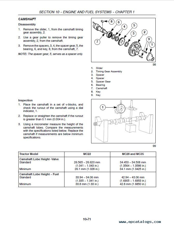
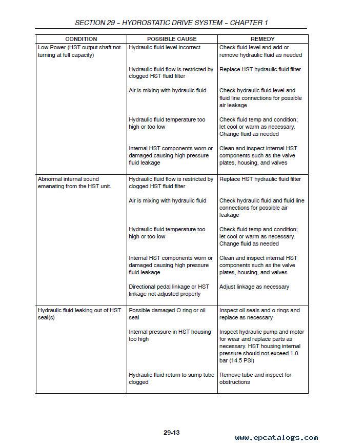
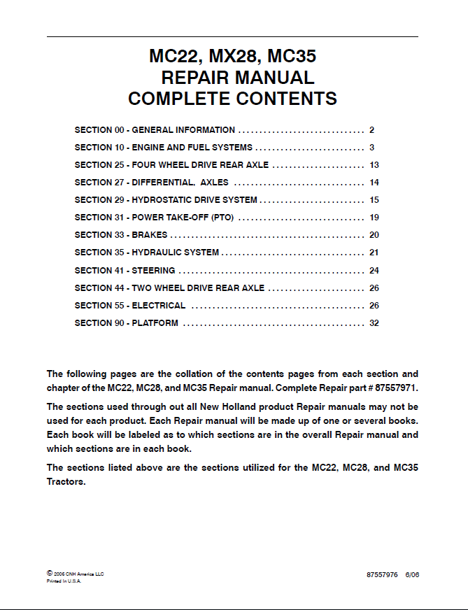
This PDF manual is a practical, mechanic-friendly guide for maintaining and repairing New Holland MC22, MX28, and MC35 commercial mowers. It replaces scattered notes and guesswork with clear procedures, torque specs, wiring logic, and exploded diagrams. If you’re troubleshooting a no-start after storage, setting valve clearances, replacing brake discs, or pressure-testing the hydraulic circuit, you’ll find step-by-step instructions and the “why” behind each step.
The manual opens with safety and general information, then moves through the machine systems the same way a technician approaches a job: diagnose, confirm, repair, verify. Procedures are written so they can be followed in the field or at the bench—minimal fluff, maximum signal.
*Every section uses clear sequences: “Removal → Disassembly → Inspection → Assembly → Installation”, with torque values and service limits where they matter.
After purchase, you’ll receive an email with a secure download link within a few minutes. If the email doesn’t show up in your inbox, check your spam or junk folder.
Right after payment, you’ll get an email with your link to download. It usually arrives within 5–7 minutes. If you don’t see it, check spam/junk.
Yes. You can print individual procedures or the entire document.
Common hand tools plus a torque wrench. Specific chapters list any special tools or gauges (for example, pressure gauges for hydraulic tests).
Yes. The electrical section includes connector pinouts, continuity tests, and interlock logic so you can test before replacing parts.
Still have questions? Leave us a message and we’ll help you get what you need.
Our company provides for sale original spare part catalogs, workshop manuals, diagnostic software for all models of engines, cars, trucks, buses, forklifts, tractors, harvesters, cranes, buldozers, generators, construction and agricultural machines, motorcycles. To purchase a catalog online, please add the product to your cart, fill in the contact form online. Our managers proceed your order the same day.
New Holland Electronic Service Tool CNH EST 9.14 [2026] Engineering Diagnostic Software![Diagnostic Software New Holland Electronic Service Tool CNH EST 9.14 [2026] Engineering Diagnostic Software](https://www.epcatalogs.com/file/base/7wA2eiQzaw96Mud+nQLe62FMZmZxTTk819fwjKwFzn9gZlueS7pErMi5cA5I4B9rnJjvyM2KHVeYq8dAqLFqg6eVylUigwGA14M6GWQO8C:2FaqSq5rLX38HGZjM8wALuylflj8yTHY6HQGzotXlCesqQ76kvVlAw5/case-new-holland-electronic-service-tools-cnh-est-software-download.webp)
The dealer software Electronic Service Tools CNH EST 9.14 update 1 (ex v9.3, v9.4, v9.5, 9.6, 9.7) with the highest engineering access Level available for download or shipping worldwide with online support!
250$
[04/2026]
|
CNH Display Codes for the Paid Features 2023 v1.1
The app generates codes for CNH displays to unlock paid features. Codes are entered through the display
3999$
[2024]
|
CNH Approval Password Generator 2023 NBV2
CNH (Case/New Holland) Generate approval passwords for Blank ECU, ECU Reassignment, and Download Crash Recovery; Supported ECU types: EDCMS62, EDC7, CNHEDC7UC31, EDC16C39.
1199$
[11/2024]
|
CNH Firmware Decrypt Encrypt Tool (FEDT) v2022.22
CNH Firmware Encrypt & Decrypt tool 2022.22 is Windows desktop software that supports decryption and encryption for *.enc and *.cre files from CNH.
999$
[12/2023]
|


© 2026 epcatalogs.com New Holland MC22, MX28, MC35 Repair Manual PDF 87557976, Heavy Technics + Repair, repair manual |
Terms of Service | DMCA Notice Of Copyright Infringement |


|