
![spare parts catalog CLAAS Parts Doc Offline Update v919 [02.2026]](/imgs/type_zapch.gif)
The Claas parts catalog 02/2026 Upd 919 features step-by-step service procedures, repair illustrations, detailed wiring diagrams, and manufacturer specifications and are easy to follow.
200$
[02/2026]
| |
| Type of catalogue: | repair manual |
| Make: | New Holland |
| Region: | WorldWide |
| Inclusive languages: |
English |
| Amount of disks: |
1 CD, 1 PDF, 1572 pages |
| Availibility | Instant Download |
| OS: | Windows XP 32 bit, Windows 7 32 bit, Windows 7 64 bit, Windows 8/8.1 32 bit, Windows 8/8.1 64 bit, Windows 10 32 bit, Windows 10 64 bit, Windows 11 64 bit, Windows 11 Pro 64 bit |
| Price, USD: | 49 |
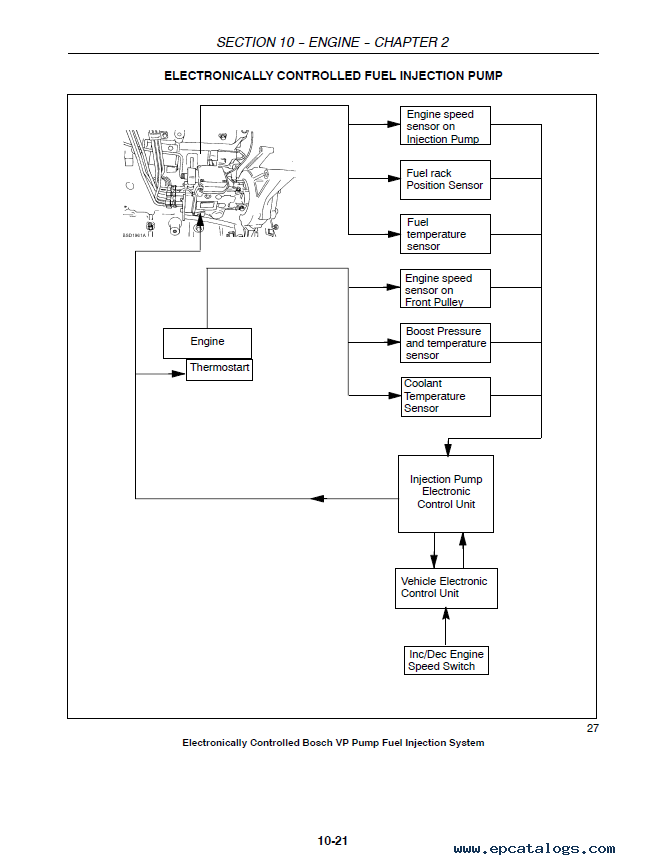
This Electronic Repair Manual provides clear, factory-style procedures for maintaining and repairing New Holland windrowers HW345 and HW365. It includes detailed descriptions, service instructions, troubleshooting guidance, hundreds of illustrations, and hydraulic/electrical diagrams so you can confidently move from diagnosis to repair.
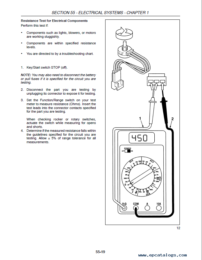
The content is organized the way technicians actually work—starting with safety and fundamentals, then moving through systems (engine, hydrostatic drive, hydraulics, brakes/controls, climate control, electrical, header attachments, rear axle, and cab/platform) with step-by-step tasks for inspection, testing, disassembly, repair, and reassembly.
Click “Buy Now,” complete the short form, and within 1–10 minutes you’ll receive an email with your secure download link and simple instructions. The file opens in any standard PDF reader, and all pages are printable. If you don’t see the message, check your spam/junk folder.
Our company provides for sale original spare part catalogs, workshop manuals, diagnostic software for all models of engines, cars, trucks, buses, forklifts, tractors, harvesters, cranes, buldozers, generators, construction and agricultural machines, motorcycles. To purchase a catalog online, please add the product to your cart, fill in the contact form online. Our managers proceed your order the same day.
New Holland Electronic Service Tool CNH EST 9.14 [2026] Engineering Diagnostic Software![Diagnostic Software New Holland Electronic Service Tool CNH EST 9.14 [2026] Engineering Diagnostic Software](https://www.epcatalogs.com/file/base/7wA2eiQzaw96Mud+nQLe62FMZmZxTTk819fwjKwFzn9gZlueS7pErMi5cA5I4B9rnJjvyM2KHVeYq8dAqLFqg6eVylUigwGA14M6GWQO8C:2FaqSq5rLX38HGZjM8wALuylflj8yTHY6HQGzotXlCesqQ76kvVlAw5/case-new-holland-electronic-service-tools-cnh-est-software-download.webp)
The dealer software Electronic Service Tools CNH EST 9.14 update 1 (ex v9.3, v9.4, v9.5, 9.6, 9.7) with the highest engineering access Level available for download or shipping worldwide with online support!
250$
[04/2026]
|
CNH Display Codes for the Paid Features 2023 v1.1
The app generates codes for CNH displays to unlock paid features. Codes are entered through the display
3999$
[2024]
|
CNH Approval Password Generator 2023 NBV2
CNH (Case/New Holland) Generate approval passwords for Blank ECU, ECU Reassignment, and Download Crash Recovery; Supported ECU types: EDCMS62, EDC7, CNHEDC7UC31, EDC16C39.
1199$
[11/2024]
|
CNH Firmware Decrypt Encrypt Tool (FEDT) v2022.22
CNH Firmware Encrypt & Decrypt tool 2022.22 is Windows desktop software that supports decryption and encryption for *.enc and *.cre files from CNH.
999$
[12/2023]
|


© 2026 epcatalogs.com New Holland HW345, HW365 Repair Manual PDF, Heavy Technics + Repair, repair manual |
Terms of Service | DMCA Notice Of Copyright Infringement |


|