New Holland Crawler Dozer D150 Workshop Manual PDF
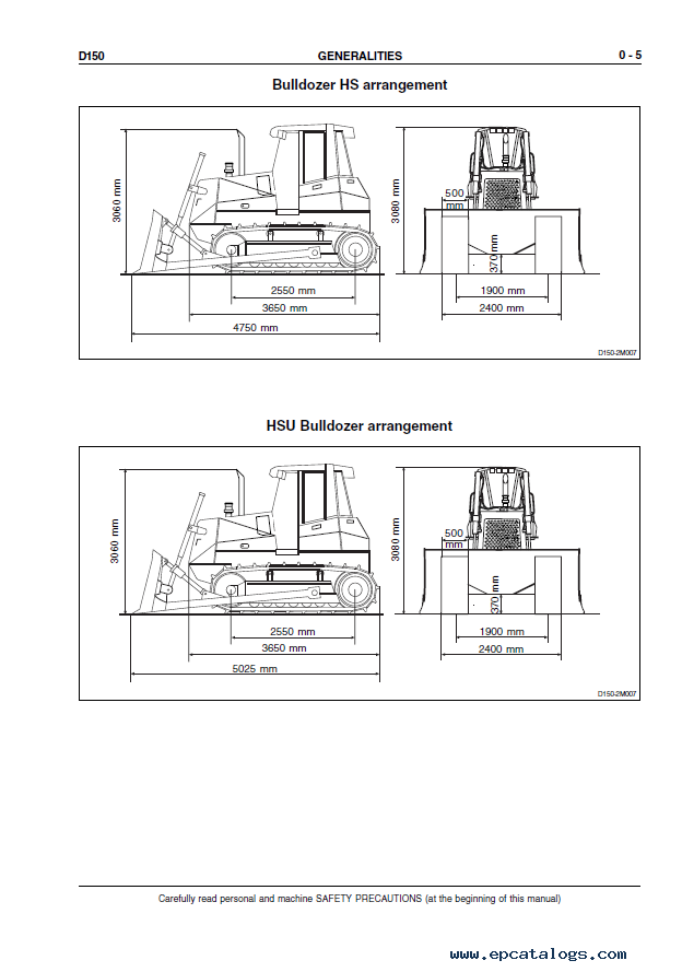
[]This manual will show you every parts and system on your crawler dozer D150. With help all this information you can distinguish a serious problem from standard maintenance and how to decide it on your own.
New Holland manual includes technical service information, schematics, service instructions, step by step recommendation for assembly and disassembly with a description, troubleshooting instructions, and many other.
Follow the step-by-step recommendations with illustrations during your work and it will be easy for you to understand the unexpected situation. The manual supports the search function to view the entire section and print the desired pages.
This workshop manual comes in PDF format on English. For high-quality transmission of all data, as well as for the correct display of charts and diagrams, we recommend installing Adobe Reader PDF.
Models:
D150
Contents:
- 0. GENERALITIES
- SAFETY RULES
- IDENTIFICATION DATA
- TABLE OF FLUID CAPACITIES
- TABLE OF CENTRE OF GRAVITY
- MAIN DIMENSIONS AND WEIGHTS
- TABLES OF TECHNICAL DATA
- CHECK DATA ON THE MACHINE
- EQUIPMENT MANOEUVRE TIMES
- LEAKAGES
- GENERAL INSTRUCTIONS
- DIAGNOSTIC CHECKS
- UNITS OF MEASURE
- TABLE OF TIGHTENING TORQUES
- 1. ENGINE
- GENERAL SPECIFICATIONS OF SERIES B ENGINE
- Engine main specifications
- Engine identification
- DESIGN FEATURES
- SERVICEABILITY
- SECURING THE ENGINE TO THE FRAME
- 2. TRANSMISSION
- GENERAL DESCRIPTION
- Transmission converter hydraulic diagram
- TROUBLESHOOTING
- TESTS
- Torque converter stall test
- Delivery pressure test procedure
- Transmission gear shifting electric control valve
- PROCEDURES FOR THE REPAIR OF THE TORQUE CONVERTER
- Removal
- Re-Installation
- Disassembly
- Reassembly
- PROCEDURES FOR THE REPAIR OF THE TRANSMISSION
- Removal
- Re-Installation
- Disassembly
- Overhaul of forwarding the speed clutch
- Overhaul of 3rd speed
- Overhaul of reverse speed clutch
- Modulating valves (Disassembly/Assembly)
- Pressure relief valve (Disassembly/Assembly)
- SPECIFICATIONS AND DATA
- General data
- Tightening torques (Torque converter)
- Tightening torques (Transmission housing)
- Transmission Data
- 3. FINAL DRIVES
- GENERAL DESCRIPTION
- Final drive (exploded view and sectional view)
- REPAIR PROCEDURES
- Final drive (removal/disassembly)
- Pulling the housing cover
- Driven gear (bearing removal)
- Driving gear shaft (bearing removal)
- Description of installation of front seals (long life)
- Final drive (assembly)
- SPECIFICATIONS AND DATA
- Final drive shaft and bearing fittings
- LIST OF OVERHAUL SPECIAL TOOLS
- 4. BRAKES AND STEERING DIFFERENTIAL
- GENERAL DESCRIPTION
- Brakes hydraulic diagram
- Main components of brakes circuit
- Steering-brakes filters
- Steering hydraulic system diagram
- Main components of steering circuit
- TROUBLESHOOTING
- Diagnosis on display
- TESTS
- Checking circuit pressures on diagnostics
- Adjusting the brake pedal
- Checks and setting on brake power valve block
- Calibration of steering levers
- REPAIR PROCEDURES
- Brake pedal valve (removal/disassembly)
- Brake power pump (removal/disassembly/re-assembly)
- Steering side group
- Bevel gear set (removal/disassembly of bevel pinion and crown gear)
- Brake group and pinion on the brake side
- Procedure and inspection for brake pack
- Procedure for the setting of the bevel pinion bearings pre-load
- (transmission side)
- Procedure for the setting of the bevel gear set
- Installation of a housing cover
- SPECIFICATIONS AND DATA
- Reduction bevel gear set
- Pinion on the brake side
- Brakes
- Brake pedal valve
- Rear transmission (transmission side section)
- LIST OF OVERHAUL SPECIAL TOOLS
- 5. UNDERCARRIAGE
- GENERAL DESCRIPTION
- Generalities
- Main components
- TROUBLESHOOTING
- Slack track chain tension
- High track chain tension
- Insufficient tightening of the screws securing the shoes to the track chain
- Working on steep slopes
- INSPECTIONS
- Inspection and adjustment of track chains
- Setting of the track tensioner pressure relief valve
- REPAIR PROCEDURES
- Track chain (removal / installation)
- Replacing a damaged link and re-installation
- Idler (removal / installation / overhaul)
- Track chain support rollers (removal / installation / overhaul)
- Track chain bottom rollers (removal / installation / overhaul)
- SPECIFICATIONS AND DATA
- Idler
- Sprockets
- Track chains
- Bottom rollers
- Support rollers
- Track tensioner device
- Front cross-member pivots
- Wear limits
- LIST OF OVERHAUL SPECIAL TOOLS
- 6. DOZER EQUIPMENT HYDRAULIC SYSTEM
- GENERAL DESCRIPTION
- Operation of the hydraulic circuit
- Diagram of dozer equipment hydraulic system
- TESTS
- Use of flow-meter
- Delivery test in the single circuits
- REPAIR PROCEDURES
- Hydraulic oil tank (removal/installation)
- Equipment hydraulic pump
- Hydraulic control valve (removal/disassembly/overhaul)
- Installation of blade
- SPECIFICATIONS AND DATA
- Hydraulic control valve
- Power hydraulic valve
- Pilot valve power valve block
- Blade lifting cylinder joint
- Blade lifting control cylinder (Angledozer version)
- Blade lifting control cylinder (Bulldozer version)
- Blade tilt cylinder (PAT version)
- Blade tilt cylinder (Bulldozer version)
- Blade angle cylinder (version PAT for STD and XLT)
- Blade angle cylinder (PAT version for LGP)
- Ripper RP12F cylinder
- Ripper RP10F cylinder
- Push beams and blade rods
- C-frame and rods
- Ripper (Version STD, XLT)
- Ripper (Version LGP)
- 7. ELECTRICAL SYSTEM
- SAFETY RULES
- PROTECTION TREE ELECTRIC DIAGRAM
- Fuses
- Fuse links and cold starting fuse
- Main switch
- Engine starting switch
- Back-up alarm
- Starter motor
- ANGLE CONTROL
- INSTRUMENT PANEL/MONITOR
- Electric diagram of the monitor instrument panel
- MONITOR SENDERS
- DISPLAY
- Diagnosis on display
- BUZZER
- RELAY GROUP - DIODE BOXES - DIVERTER BOX
- 19 - 21 - 23 WAYS CONNECTORS
- 8. AIR CONDITIONING UNIT
- AIR CONDITIONING UNIT
- Operating instructions
- Technical data
- Cab climate conditioner and error codes
- Service precautions
- Tool connections
- Discharging
- Refrigerant charging
- Leak inspection
- Special tools
- Troubleshooting
Screenshots for New Holland Crawler Dozer D150 Workshop Manual PDF:
Our company provides for sale original spare part catalogs, workshop manuals, diagnostic software for all models of engines, cars, trucks, buses, forklifts, tractors, harvesters, cranes, buldozers, generators, construction and agricultural machines, motorcycles. To purchase a catalog online, please add the product to your cart, fill in the contact form online. Our managers proceed your order the same day.
Related products for New Holland Crawler Dozer D150 Workshop Manual PDF:
![]() eTimGo AGCE for CNH EST 2025 all brands OFFLINE
eTimGo AGCE for CNH EST 05/2025 all brands OFFLINE. Manuals, electrical bulletin diagrams, and diagnostic procedures are provided, including some spare parts catalogs.
1200$
[05/2025]
|
New Holland Electronic Service Tool CNH EST 9.13 [2026] Engineering Diagnostic Software
The dealer software Electronic Service Tools CNH EST 9.13 update 3 (ex v9.3, v9.4, v9.5, 9.6, 9.7) with the highest engineering access Level available for download or shipping worldwide with online support!
250$
[01/2026]
|
Original CNH DPA5 Diagnostic Service Tool Adapter Cable Kit + CNH EST 9.12
The Case, New Holland (CNH) DPA5 adapter kit includes all the cables. This is a genuine CNH DPA5 kit. Include CNH 9.12 Engineering Software 2025
1699$
[2025]
|
CNH Display Codes for the Paid Features 2023 v1.1
The app generates codes for CNH displays to unlock paid features. Codes are entered through the display
3999$
[2024]
|


