This PDF workshop manual gives the main instructions on how to repair Lombardini Diesel Engines LDW 502-602-903-1204-1204/T e LDW 702-1003-1404.
The manual determines the purpose for which the engines are arranged and contains all the necessary service information to ensure safe and proper engine management. This service manual is an integral part of the engine because it must be maintained with care and helps to monitor the engine itself.
All repair information and operating instructions contained in this repair manual are verified and evaluated by the manufacturer.
This workshop manual is quite simple to use even for inexperienced users since it is a PDF document. To work with the manual, it is enough to install on your device the Adobe PDF Reader application (or any other program equivalent). Study this workshop manual in more details with the help of a detailed list of content "INDEX" that is presented below. For convenience, you can print the entire manual and use it as a book if necessary.
Document code 1-5302-351
Models covered:
LDW 502-602-903-1204-1204/T,
LDW 702-1003-1404.
INDEX:
- 1 GENERAL REMARKS AND SAFETY INFORMATION
- General safety during operating phases
- General service manual notes
- Glossary and terminology
- Safety and environmental impact
- Safety and warning decals
- Safety regulations
- Warranty certificate
- 2 TECHNICAL INFORMATION
- Manufacturer and engine identification
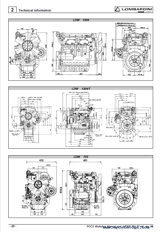
- Overall dimension
- Performance diagrams
- Technical specifications
- Troubleshooting
- 3 MAINTENANCE - RECOMMENDED OIL TYPE - REFILLING
- ACEA Regualtions - ACEA Sequences
- API / MIL Sequences
- Coolant
- Fuel specifications
- International specifications
- Lubricant
- Prescribed lubricant
- Routine engine maintenance
- SAE Classification
- 4 DISASSEMBLY/REASSEMBLY
- Air filter support
- Air restriction switch
- Alternator/Cooling fan belt drive
- Big end bearing
- Camshaft journals and bushings - Dimensions
- Camshaft lobe measurement
- Camshaft timing - Belt Reassembly
- Camshaft timing - Belt Tightening and Fastening
- Camshaft timing - Belt tightening tool
- Camshaft timing pulley - Disassembly/Assembly
- Camshaft timing pulley - Reference marks
- Camshaft, disassembly
- Camshaft, journal and housing measurement
- Central main bearing caps
- Check the clearances between the bearings and the journal
- Clearances between the bearings and corresponding pins
- Connecting rod
- Connecting rod alignment
- Connecting rod with bearings and pin
- Connecting tod, weight
- Cooling fan
- Crankcase breather LDW 502
- Crankcase vacuum regulator valve
- Crankshaft axial clearance
- Crankshaft front and back oil seal rings
- Crankshaft timing pulley
- Crankshaft, check journals and crank
- Crankshaft, lubrication lines
- Cylinder head assembly
- Cylinder head tightening procedure LDW 1204-1204/T-1404
- Cylinder head tightening procedure LDW 502-602-702-903-1003
- CYLINDER HEAD, removal
- Cylinder roughness
- Cylinder, class
- Cylinders
- Driving pulley
- Dry type air filter
- E.G.R. Circuit
- Exhaust maniflod
- Flywheel
- Fuel rail
- Fuel tank (optional)
- Governor springs
- Governor springs for Gensets
- Head gasket
- Hydraulic pump drive
- Injection pump control rod
- Intake / Exhaust / Injection camshaft lobe height - LDW 903
- Intake manifold – Remote air filter
- Journal and connecting rod pins diameters
- Main bearings and connecting rod big ends diameters
- Oil bath air cleaner (on request)
- Oil pan, removal
- Oil pump - disassembly
- Oil pump - Reassembly
- Piston
- Piston clearance
- Piston coolant nozzles
- Piston ring, Clearance between grooves
- Piston ring, mounting order
- Piston rings - End gaps
- Piston, assembly
- Piston, class
- Piston, disassembly and inspection
- Piston, weight
- Pre-combustion chamber
- Pre-combustion chamber ring nut removal
- Pre-combustion chamber, installation
- Pre-combustion chamber, removal
- Pump/injector unit - Disassembly
- Pump/injector unit - non-return valve
- Rear and forward main bearing caps
- Recommendations for disassembling and assembling
- Recommendations for overhauls and tuning
- Return pulley
- Ringfeder-type rings on LDW 1204-1204/T-1404
- Ringfeder-type rings on LDW 1204-1204/T-1404 - Assembly
- Rocker arm assembly
- Rocker arm cover
- Rocker arm cover gasket
- Rocker arm pivot, dismounting and remounting
- Shoulder half rings
- Shoulder half rings, oversized elements
- Speed governor
- Speed governor - Limiting speed governor
- Speed governor - Reassembly
- Speed governor components
- Stop pin rings, dismounting and remounting
- Third drive, components
- Tightening pulley
- Timing belt / Timing pulley arrangement
- Timing belt cover
- Timing belt removal
- Vacuum pump and vacuum pump flange
- Valve / Rocker arm clearance
- Valve guide insertion
- Valve guides and valve guide housings
- Valve recess and seat sealing width
- Valve seats and housings - Dimensions
- Valve springs
- Valve stem sealing rings - Reassembly
- Valve timing - Angles
- Valve timing check
- Valve, specifications
- Valves
- 5 TURBOCHARGER
- Turbocharger
- Turbocharger components
- Turbocharger pressure testing
- Turbocharger west gate adjustment - Regolazione corsa asta comando valvola " Waste gate "
- 6 LUBRIFICATION CIRCUIT
- Internal oil filter and oil sump return pipe
- Lubrification circuit
- Oil filter cartridge
- Oil pressure check
- Oil pressure regulating valve
- Oil pump
- Oil pump, clearance between rotors
- 7 COOLANT CIRCUIT
- Coolant circuit
- Coolant circulation pump, components
- Radiator and compensation, check and seal tank cap
- Thermostatic valve
- 8 FUEL SYSTEM
- Closing the oilhole
- Fuel feeding / injection circuit
- Fuel filter detached from the tank (on request)
- Fuel lift pump
- Fuel pump drive rod projection
- Injection advance control and regulation
- Injection advance for currently used pump/injector unit
- Injection advance references on timing belt protector
- Injection pump assembly/disassembly
- Injection pumps delivery balancing
- Injector, nozzle projection
- Injector, setting (old type)
- Injector, spark arrester
- Instrument connection
- Plunger barrel ring nut assembly/disassembly
- Plunger injection pump reassembly
- Preliminary steps to pump/injector unit delivery balancing test
- Pump/injector unit
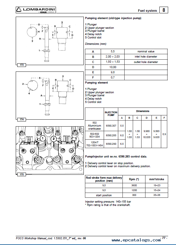
- Pump/injector unit se.no. 6590.285 control data
- Pump/injector unit, components
- Pumping element
- Pumping element (old-type injection pump)
- Setting of injector according to current pump/injector unit
- Static injection advance regulation
- Static injection advance tuning
- TDC (Top Dead Center) references
- Test head B assembly
- Tester and special coupling for injection advance control (Old-type injection pump)
- 9 ELECTRIC SYSTEM
- Alternator battery charger curve 12V 20A
- Alternator battery charger curve 12V 30A
- Alternator type Iskra, 14V 33A
- Alternator type Iskra, 14V 33A - Performance Curve
- Alternator, Marelli type AA 125 R 14V 45A
- Alternator, Marelli type AA 125 R 14V 45A - Performance Curve
- Coolant high temperature lamp sensor
- Electric control panel with automatic engine stop
- Electric starting layout (12V) with flywheel alternator
- Electric starting layout (12V) with Iskra alternator 14V 33A
- Electric starting layout (12V) with Marelli type AA 125 R 14V 45A alternator
- Flywheel Alternator
- Oil pressure switch
- Pre-heating glow plug
- Pre-heating glow plug control unit with coolant temperature sensor
- Starter motor - Bosch DW 12V 1,1 KW
- Starter motor, Bosch 12V 1,6 Kw
- Starter motor, Bosch DW 12V 1,1 KW - Performance Curve
- Starter motor, Bosch DW 12V 1,6 KW - Performance Curve
- Temperature sensor for control unit
- Voltage regulator connections
- 10 SETTINGS
- E.G.R. calibration
- Injection pump flow limiter and standard enigne torque gearing device
- Pump injection delivery standard setting without dynamometric brake
- Pump/injector unit delivery setting with braked engine
- Pump/injector unit timing with speed governor
- Required settings (as most commonly applies)
- Setting the idle maximum (standard)
- Setting the idle minimum (standard)
- Setting the stop
- Speed settings
- 11 STORAGE
- Engine storage (not installed)
- Preparing the engine for operation after protective treatment
- Protective treatment
- 12 TORQUE SPECIFICATIONS AND USE OF SEALANT
- Table of tightening torques for standard screws (coarse thread)
- Table of tightening torques for standard screws (fine thread)
- Table of tightening torques for the main components
- 13 SPECIAL TOOLS
Our company provides for sale original spare part catalogs, workshop manuals, diagnostic software for all models of engines, cars, trucks, buses, forklifts, tractors, harvesters, cranes, buldozers, generators, construction and agricultural machines, motorcycles. To purchase a catalog online, please add the product to your cart, fill in the contact form online. Our managers proceed your order the same day.


![spare parts catalog CLAAS Parts Doc Offline Update v919 [02.2026]](/imgs/type_zapch.gif)