Lombardini engines are designed to provide safe and long-lasting performance, but to achieve this result, it is imperative that the maintenance requirements described in the manual are met along with the safety regulations. In order to maintain the proper working condition, you need to purchase this PDF workshop manual.
This service manual contains detailed service information, technical data, diagrams, illustrations and other instructions for Lombardini Engines CHD Series (that are installed on JCB equipment).
This workshop manual contains detailed tables that contain possible causes of some faults. These faults may occur during engine operation. Therefore, this troubleshooting and repair information will be very helpful in the maintenance and operation of the engine.
This repair manual is quite simple to use even for inexperienced users since it is a PDF document. To work with the manual, it is enough to install on your device the Adobe PDF Reader application (or any other program equivalent). For convenience, you can print the entire manual and use it as a book if necessary.
Document code 1-5302-345
Models covered:
LDW 1503 - 1603 - 2004 - 2004/T - 2204 - 2204/T
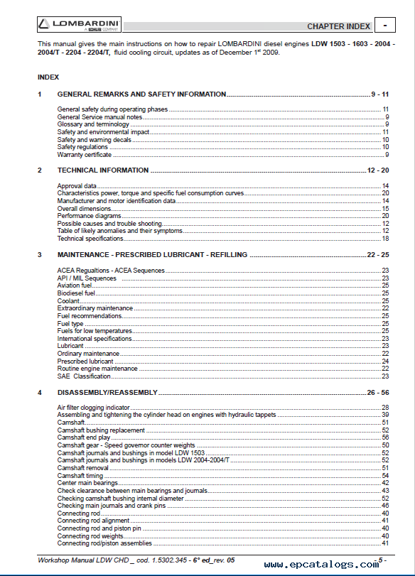
INDEX:
- 1 GENERAL REMARKS AND SAFETY INFORMATION
- General safety during operating phases
- General Service manual notes
- Glossary and terminology
- Safety and environmental impact
- Safety and warning decals
- Safety regulations
- Warranty certificate
- 2 TECHNICAL INFORMATION
- Approval data
- Characteristics of power, torque, and specific fuel consumption curves
- Manufacturer and motor identification data
- Overall dimensions
- Performance diagrams
- Possible causes and troubleshooting
- Table of likely anomalies and their symptoms
- Technical specifications
- 3 MAINTENANCE - PRESCRIBED LUBRICANT - REFILLING
- ACEA Regulations - ACEA Sequences
- API / MIL Sequences
- Aviation fuel
- Biodiesel fuel
- Coolant
- Extraordinary maintenance
- Fuel recommendations
- Fuel type
- Fuels for low temperatures
- International specifications
- Lubricant
- Ordinary maintenance
- Prescribed lubricant
- Routine engine maintenance
- SAE Classification
- 4 DISASSEMBLY/REASSEMBLY
- Air filter clogging indicator
- Assembling and tightening the cylinder head on engines with hydraulic tappets
- Camshaft
- Camshaft bushing replacement
- Camshaft endplay
- Camshaft gear - Speed governor counterweights
- Camshaft journals and bushings in model LDW 1503
- Camshaft journals and bushings in models LDW 2004-2004/T
- Camshaft removal
- Camshaft timing
- Center main bearings
- Check clearance between main bearings and journals
- Checking camshaft bushing internal diameter
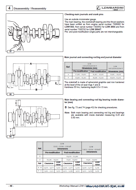
- Checking main journals and crankpins
- Connecting rod
- Connecting rod alignment
- Connecting rod and piston pin
- Connecting rod weights
- Connecting rod/piston assemblies
- Cooling fan
- Crankshaft endplay
- Crankshaft for engines with a dynamic equalizer (only four-cylinder engines)
- Crankshaft front and rear oil seal
- Crankshaft lubrication ducts
- Crankshaft timing gear
- Cylinder head
- Cylinder head gasket
- Cylinder head tightening for engines without hydraulic tappets
- Cylinder head tightening steps
- Cylinder roughness
- Cylinders
- Dimensions for injection pump delivery control yoke adjustment
- Driving pulley (2a P.T.O.)
- Dry air cleaner
- Dry air components
- Dynamic balancer (on request) - Adjustment of clearance between teeth D and ring gear A
- Engines with hydraulic tappets
- Engines with mechanical tappets
- Exhaust manifold
- Flywheel
- Frame with idling speed governor spring
- Front cover
- GR 1 and GR 2 hydraulic pump 3rd p.t.o.
- Hydraulic diagram for feeding the tappets
- Hydraulic pump p.t.o.
- Hydraulic tappet components
- Hydraulic tappet operation
- Hydraulic tappet valve control
- Idler gear and hub
- Injection pump follower
- Intake manifold
- Intake, exhaust and injection cam height for models LDW 2004- 2004/T
- Intake, exhaust and injection cam height for model LDW 1503
- Main bearing and connecting rod big bearing inside diameter (mm)
- Main bearing caps timing side - flywheel side
- Main journal and connecting rod big end journal diameter
- Oil seal in the valves guides, (intake and exhaust)
- Oil-bath air cleaner
- Oil-bath air cleaner components
- Piston
- Piston - Refitting
- Piston availability
- Piston cooling sprayer
- Piston position and clearance
- Piston rings - Clearance between grooves
- Piston rings - End gaps
- Piston rings - Fitting sequence
- Piston weight
- Precombustion chamber
- Recommendations for disassembling and assembling
- Recommendations for overhauls and tuning
- Rocker arm assembly
- Rocker arm cover for engines with recirculating vent
- Rocker arm cover with vent into the air
- Speed governor
- Speed governor counter springs
- Spring for extra fuel supply at starting
- Summary tables of the governor equipment according to the speed variation
- Table of pin-rocker arm dimensions
- Tank
- Thrust bearing, oversizes
- Thrust bearings
- Timing angles for checking purposes
- Timing angles for checking purposes LDW 2004/T
- Timing angles for operating purposes
- Timing angles for operating purposes LDW 2004/T
- Timing belt operating angles (with valve clearance set to zero)
- V belt
- Valve guide insertion, after driving
- Valve guides and cylinder head
- Valve material
- Valve recess and sealing surfaces
- Valve removal
- Valve seats and bore
- Valve spring - Check
- Valve spring - check under load
- Valve timing check
- Valve timing without considering timing marks
- 5 TURBOCHARGER
- Checking actuator setting - "Wastegate" valve control rod stroke adjustment
- Turbocharger
- Turbocharger components
- Turbocharger Testing
- 6 LUBRICATION SYSTEM
- Lubrication system layout
- Oil filter cartridge
- Oil pressure adjusting valve
- Oil pressure check
- Oil pressure curve for LDW 1503 - 1603
- Oil pressure curve for LDW 2004 - 2204
- Oil pressure curve for LDW 2004/T - 2204/T
- Oil pump
- Oil pump rotor clearance
- 7 COOLING SYSTEM
- Cooling system layout
- Expansion tank and cap
- Checking for cooling system leaks
- Coolant circulating pump
- Thermostat
- 8 FUEL SYSTEM
- Checking injection pump delivery
- Checking low-pressure injection timing for engines with hydraulic tappets
- Checking low-pressure injection timing for engines with mechanical tappets
- Electric fuel pump (24V)
- Fuel feeding pump
- Fuel feeding pump drive rod protrusion
- Fuel feeding/injection circuit
- Fuel filter
- How to reassemble injection pump components
- How to reassemble injection pump feeding tubes
- How to remove injection pump feeding tubes
- Injection pump
- Injection pump control rod
- Injection pump delivery equalization
- Injection pump disassembly
- Injection pump non-return valve
- Injection pump P. No. 6590-249 - Plunger and barrel assembly
- Injection timing correction by changing the pad thickness
- The injector (pin type)
- Injector setting
- An instrument for equalizing injection pump delivery
- Test data of injection pump
- 9 ELECTRIC SYSTEM
- Alternator type Iskra, AAK3139 14V 80A
- Alternator type Iskra, type AAK3570 28V 35A (for 24 V outfits)
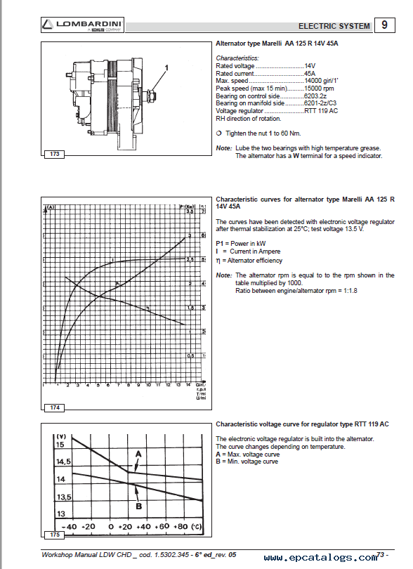
- Alternator type Marelli AA 125 R 14V 45A
- Alternator type Marelli AA 125 R 14V 65A
- Characteristic curves for alternator type AAK3570 28V 35A (for 24 V outfits)
- Characteristic curves for alternator type Iskra, AAK3139 14V 80A
- Characteristic curves for alternator type Marelli AA 125 R 14V 45A
- Characteristic curves for alternator type Marelli AA 125 R 14V 65A
- Characteristic curves for starting motor Iskra type AZE 4598 24V 3 kW
- Characteristic curves for starting motor type Bosch EV 12V 2.2 kW
- Characteristic voltage curve for regulator type AER 1528
- Characteristic voltage curve for regulator type AER 1528
- Characteristic voltage curve for regulator type RTT 119 AC
- Characteristic voltage curve for regulator type RTT 119 AC
- Connection diagram for preheating control unit
- Connection diagram for preheating control unit
- Coolant high-temperature lamp switch
- Glow plug controller relay with coolant temperature sensor
- Heavy starting conditions (max admitted)
- Heavy starting conditions (max admitted)
- Key switch electrical layout
- Key switch electrical layout
- Normal starting conditions
- Normal starting conditions
- Pre-heating glow plug
- Spacer flange for starter motor
- Starting Motor 12V
- Starting Motor 24V
- Temperature sensor (Thermistor)
- Thermistor for an electric thermometer
- Thermistor for preheating water temperature – Thermal contact for water temperature indicator light
- Wiring diagram 24 V with alternator 35A
- Wiring diagram with alternator 45A / 65A
- 10 SETTINGS
- Application diagram for tampering system adjustment screw and torque gearing device for EPA-approved engines
- Fuel limiting device
- Fuel limiting device adjustment
- Full speed setting in no-load conditions (standard)
- Idling speed setting in no-load conditions (standard)
- Injection pump delivery limiting and torque adjusting device
- Standard injection pump delivery setting without torque dynamometer
- Stop setting
- 11 ENGINE STORAGE
- Engine storage
- Preparing the engine for operation after protective treatment
- Protective treatment
- 12 TORQUE SPECIFICATIONS AND USE OF SEALANT
- Main torque specifications
- Table of tightening torques for standard screws (coarse thread)
- Table of tightening torques for standard screws (fine thread)
- 13 SPECIAL TOOLS
Our company provides for sale original spare part catalogs, workshop manuals, diagnostic software for all models of engines, cars, trucks, buses, forklifts, tractors, harvesters, cranes, buldozers, generators, construction and agricultural machines, motorcycles. To purchase a catalog online, please add the product to your cart, fill in the contact form online. Our managers proceed your order the same day.


![spare parts catalog CLAAS Parts Doc Offline Update v919 [02.2026]](/imgs/type_zapch.gif)