This PDF Component Technical Manual contains detailed technical service and routine maintenance information, special repair instructions, technical data, specifications for John Deere Diesel Engines Series 300 3179, 4239, 6359, 4276, 6414.
This component technical manual contains complete information on the maintenance of engines John Deere. It covers detailed descriptions of the work on the maintenance and repair of John Deere engines. This manual is written for an experienced technician. Essential tools required in performing certain service work are identified in this manual and are recommended for use.
Information is organized in groups for the various components requiring service instruction. At the beginning of each group are summary listings of all applicable essential tools, service equipment, and tools, other materials needed to do the job, service parts kits, specifications, wear tolerances, and torque values.
The CTM comes in PDF and includes 547 pages, which are printable. It does not require installation (INSTANT DOWNLOAD). To work with the PDF manual, we recommend that you use the Adobe Acrobat Reader application.
For your convenience, we present you with a link 'John Deere pdf manual instant preview' on the top of this page. This link will help you to preview this PDF manual and understand that this manual contains needed for your service information or not.
Document Part Number: CTM4
Models covered:
300 Series
3179,
4239,
6359,
4276,
6414.
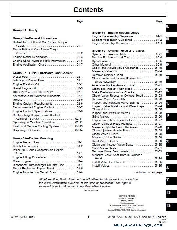
CONTANTS:
- Group 00—Safety
- Group 01—General Information
- Unified Inch Bolt and Cap Screw Torque Values
- Metric Bolt and Cap Screw Torque Values
- Engine Model Designation
- Engine Serial Number Plate Information
- Engine Application Chart
- Group 02—Fuels, Lubricants, and Coolant
- Diesel Fuel
- Lubricity of Diesel Fuels
- Engine Break-In Oil
- Diesel Engine Oil
- OILSCAN® and COOLSCAN™
- Alternative and Synthetic Lubricants
- Grease
- Engine Coolant Requirements
- Recommended Engine Coolant
- Engine Coolant Specifications
- Replenishing Supplemental Coolant Additives (SCA’s) Between Coolant Changes
- Operating in Tropical Conditions
- Flush and Service Cooling System
- Disposing of Coolant
- Group 03—Engine Mounting
- Engine Repair Stand
- Safety Precautions
- Install 300 Series Adapters on Repair Stand
- Engine Lifting Procedure
- Clean Engine
- Disconnect Turbocharger Oil Inlet Line
- Mount Engine on Repair Stand
- Engine Mounted on Repair Stand
- Group 04—Engine Rebuild Guide
- Engine Disassembly Sequence
- Sealant Application Guidelines
- Engine Assembly Sequence
- Group 05—Cylinder Head and Valves
- Special or Essential Tools
- Service Equipment and Tools
- Specifications
- Other Material
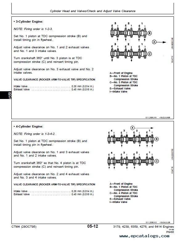
- Check and Adjust Valve Clearance
- Measure Valve Lift
- Remove Cylinder Head
- Disassemble and Inspect Rocker Arm Shaft Assembly
- Assemble Rocker Arms on Shaft
- Clean and Inspect Push Rods
- Make Preliminary Valve Checks
- Check Valve Recess in Cylinder Head
- Remove Valve Assembly
- Inspect and Measure Valve Springs
- Inspect Valve Rotators and Wear Caps
- Clean Valves
- Inspect and Measure Valves
- Grind Valves
- Inspect and Clean Cylinder Head
- Check Cylinder Head Flatness
- Measure Cylinder Head Thickness
- Clean Injection Nozzle Bores
- Clean Valve Guides
- Measure Valve Guides
- Knurl Valve Guides
- Clean and Inspect Valve Seats
- Grind Valve Seats
- Remove Valve Seat Inserts
- Measure Valve Seat Bore in Cylinder Head
- Install Valve Seat Inserts
- Install Valves
- Valve Stem Seals—General Information
- Install Valve Stem O-Ring Seals
- Install Valve Stem Tower Seals
- Inspect and Clean Ventilator Outlet Hose
- Inspect and Clean Exhaust Manifold
- Clean and Inspect Top Deck of Cylinder Block
- Measure Cylinder Liner Standout (Height Above Block)
- Clean and Inspect Cylinder Head Cap Screws
- Install Cylinder Head
- Install Cylinder Head Cap Screws
- TORQUE-TURN Method for Proper Torque Install Rocker Arm Assembly
- Install Rocker Arm Cover
- Complete Final Assembly
- Perform Engine Break-In
- Group 10—Cylinder Block, Liners, Pistons, and Rods
- Special or Essential Tools
- Service Equipment and Tools
- Other Material
- Specifications
- Remove Pistons and Connecting Rods
- Remove Cylinder Liners
- Complete Disassembly of Cylinder Block (If Required) Preliminary Liner, Piston and Rod Checks.
- Disassemble Piston and Rod Assembly
- Clean Pistons
- Visually Inspect Pistons
- Install Piston Pin
- Clean Cylinder Liners
- Visually Inspect Cylinder Liners
- Check Piston Ring Groove Wear
- Measure Piston Skirt
- Determine Piston-to-Liner Clearance
- Deglaze Cylinder Liners
- Replace Piston and Liner Sets
- Determine Piston Type
- Measure Piston Protrusion
- Inspect and Measure Connecting Rod Bearings
- Inspect Rod and Cap
- Inspect Piston Pins and Bushings
- Remove Piston Pin Bushing
- Clean and Inspect Connecting Rod Pin Bore
- Install Piston Pin Bushing in Connecting Rod
- Inspect and Clean Cylinder Block
- Clean Cylinder Liner O-Ring Bore
- Measure Cylinder Block Main Bearing Bore
- Measure Camshaft Follower Bore
- Measure Camshaft Bearing Bore
- Measure Balancer Shaft Bore—4-Cylinder Engines
- Measure Cylinder Block Top Deck Flatness
- Inspect Piston Cooling Orifices
- Measure Liner Flange Thickness and Block Counterbore Depth
- Recheck Cylinder Liner Standout (Height Above Block)
- Install Steel Ball in Oil Passage of Service Cylinder Block
- Install Cylinder Liner O-Rings and Packings
- Install Cylinder Liner
- Assemble Piston and Connecting Rod
- Install Piston Rings
- Install Piston and Connecting Rod Assembly
- Check Engine Rotation For Excessive Tightness
- Measure Piston Protrusion
- Complete Final Assembly
- Group 15—Crankshaft, Main Bearings, and Flywheel
- Special or Essential Tools
- Service Equipment and Tools
- Specifications
- Other Material
- Crankshaft and Main Bearing Failure Analysis
- Inspect Vibration Damper (6-Cylinder Engine)
- Remove Pulley or Vibration Damper Pulley
- Install Pulley or Vibration Damper Pulley
- Checking Vibration Damper or Pulley (Front PTO)
- Removing Vibration Damper or Pulley (Front PTO)
- Install Vibration Damper or Pulley (Front PTO)
- Replace Front Crankshaft Oil Seal (Without Removing Cover)
- Check Crankshaft End Play
- Inspect Flywheel
- Check Flywheel Housing Face Runout
- Check Flywheel Face Flatness
- Remove Flywheel
- Replace Flywheel Ring Gear
- Install Flywheel
- Crankshaft Rear Oil Seal and Wear Sleeve General Information
- Remove Two-Piece Crankshaft Oil Seal and Wear Sleeve
- Remove Unitized Crankshaft Rear Oil Seal and Wear Sleeve
- Install Crankshaft Rear Oil Seal and Wear Sleeve
- Remove Flywheel Housing
- Remove Crankshaft Main Bearings
- Check Main Bearing Clearance
- Remove and Install Crankshaft Gear with Crankshaft Installed
- Remove Crankshaft
- Remove Crankshaft Rear Wear Sleeve with Crankshaft Removed
- Inspect Crankshaft
- Measure Assembled ID of Bearings and OD of Crankshaft Journal
- Measure Main Thrust Journal Width and Thrust Bearing Width
- Crankshaft Grinding Guidelines
- Crankshaft Grinding Specifications
- Measure Assembled ID of Main Bearing Caps
- Inspect Piston Cooling Orifices
- Install Main and Thrust Bearing Inserts in Block
- Install Crankshaft
- Install Flywheel Housing
- Complete Final Assembly
- Group 16—Camshaft, Balancer Shafts, and Timing Gear Train
- Special or Essential Tools
- Service Equipment and Tools
- Other Materials
- Specifications
- Auxiliary Gear Drive Specifications
- Measure Valve Lift
- Remove Timing Gear Cover
- Remove Auxiliary Drive Gears
- Measure Camshaft End Play
- Measure Balancer Shaft End Play—4-Cylinder Engines
- Measure Timing Gear Backlash
- Measure Idler Gear End Play
- Remove Camshaft
- Visually Inspect Camshaft
- Measure Camshaft Thrust Plate Clearance
- Inspect and Measure Camshaft Bearing Bore ID and Journal OD
- Measure Camshaft Lobe Height
- Remove and Install Camshaft Gear
- Inspect Camshaft Followers
- Replace Tachometer Drive Gear
- Remove Balancer Shafts—If Equipped (4-Cylinder Engines)
- Inspect and Measure Balancer Shaft Bushings and Journals
- Remove and Install Balancer Shaft Bushings in Block
- Install Oversize Balancer Shaft Bushings in Block—4239 Engines
- Inspect Balancer Shaft Gears and Thrust Plates
- Remove and Install Balancer Shaft Gears
- Remove Balancer Shaft
- Remove Cylinder Block Front Plate
- Measure Idler Gear Bushing and Shaft
- Remove and Install Idler Gear Bushings
- Remove Lower and Upper Idler Shafts
- Clean and Inspect Front Plate
- Replace Engine Front Plate
- Transfer Fuel Injection Pump Timing Mark Onto Replacement Front Plate
- Install Idler Shaft Spring Pins
- Install Upper Idler Shaft in Front Plate
- Install Lower Idler Shaft in Front Plate
- Install Engine Front Plate
- Install and Time Balancer Shafts—If Equipped (4-Cylinder Engines)
- Install and Time Camshaft and Fuel Injection Pump
- Clean and Inspect Timing Gear Cover
- Install Ball Bearings and Dowels
- Install Drive Gear
- Install Timing Gear Cover
- Install Crankshaft Front Oil Seal
- Install Idler Gear and Output Gear
- Complete Final Assembly
- Group 20—Lubrication System
- Special or Essential Tools
- Service Equipment and Tools
- Other Material
- Specifications
- Engine Crankcase Oil Fill Quantities
- Identify Oil Cooler Type—3179, 4239, 6359 Engines
- Remove, Inspect, & Install Standard-Flow Oil Cooler (3179, 4239, 6359)
- Remove and Install High-Flow Oil Cooler (6359 Engines)
- Remove Distributor Base—High-Flow Cooler (6359)
- Inspect and Repair Distributor Base—High Flow Oil Cooler (6359)
- Install Distributor Base—High-Flow Oil Cooler (6359)
- Remove Oil Cooler (4276, 6414 Engines)
- Repair Oil Cooler (4276, 6414 Engines)
- Install Oil Cooler (4276, 6414 Engines)
- Remove and Inspect Oil Bypass Valve (3179, 4239, 6359 Engines)
- Measure Oil Bypass Valve Length and Cylinder Block Bore
- Install Oil Bypass Valve (3179, 4239, 6359 Engines)
- Remove and Install Oil Cooler/Filter Bypass Valve (4276, 6414 Engines)
- Remove & Install Oil Pressure Regulating Valve/Seat (3179, 4239, 6359)
- Remove, Inspect and Install Oil Pressure Regulating Valve (4276, 6414)
- Repair Oil Pressure Regulating Valve (4276, 6414 Engines)
- Remove Oil Filter Adapter (3179, 4239, 6359 Engines)
- Install Oil Filter Adapter (3179, 4239, 6359 Engines)
- Remove, Install, and Adjust Dipstick Tube
- General Oil Pump Information
- Replace Oil Pump Pick-Up Tube Assembly
- Remove Standard Capacity Oil Pump
- Inspect and Measure Clearances (Standard Capacity Oil Pump)
- Complete Standard Capacity Oil Pump Disassembly
- Assemble Standard Capacity Oil Pump
- Install Standard Capacity Oil Pump
- Remove High Capacity Oil Pump
- Inspect and Measure Clearances (High Capacity Oil Pump)
- Complete High Capacity Oil Pump Disassembly
- Assemble High Capacity Oil Pump
- Install High Capacity Oil Pump
- Install Oil Pan
- Group 25—Cooling System
- Special or Essential Tools
- Service Equipment and Tools
- Other Material
- Specifications
- Remove, Test, and Install Thermostats
- Remove and Install Thermostat Housing/Water Manifold
- General Water Pump Information
- Remove Low Flow (Standard Duty) Water Pump
- Disassemble Low Flow (Standard Duty) Water Pump
- Inspect and Clean Low Flow (Standard Duty) Water Pump Parts
- Assemble Low Flow (Standard Duty) Water Pump
- Install Low Flow (Standard Duty) Water Pump
- Remove High Flow (Heavy-Duty) Water Pump
- Disassemble High Flow (Heavy-Duty) Water Pump
- Inspect and Clean High Flow (Heavy-Duty) Water Pump Parts
- Assemble High Flow (Heavy-Duty) Water Pump
- Checking Water Pump Cap Screw Protrusion
- Install High Flow (Heavy-Duty) Water Pump
- Inspect and Install Fan Blade Assembly
- Remove Coolant Heater—If Equipped
- Install Coolant Heater—If Equipped
- Group 30—Air Intake and Exhaust System
- Other Material
- Specifications
- Extending Turbocharger Life
- Remove Turbocharger—4239T and 6359T & A Engines
- Turbocharger Failure Analysis
- Turbocharger Seven-Step Inspection
- Perform Radial Bearing Clearance Test—K.K.K
- Perform Axial Bearing End Play Test—K.K.K
- Perform Radial Bearing Clearance Test—AiResearch/Garrett
- Perform Axial Bearing End Play Test—AiResearch/Garrett
- Repair Turbocharger
- Disassemble and Inspect Turbocharger
- Replace Center Housing and Rotating Assembly
- Prelube Turbocharger
- Install K.K.K. and AiResearch/Garrett Turbocharger
- Turbocharger Break-In
- Remove, Inspect, and Install Intake Manifold
- Remove Cross-Over Tube Assembly—If Equipped
- Inspect and Repair Cross-Over Tube Assembly—If Equipped
- Install Cross-Over Tube Assembly—If Equipped
- Remove Aftercooler and Intake Manifold (6359A)
- Inspect and Repair Aftercooler (6359A)
- Inspect and Repair Intake Manifold (6359A)
- Install Intake Manifold and Aftercooler (6359A)
- Remove, Inspect, and Install Exhaust Manifold
- Group 35—Fuel System
- Special or Essential Tools
- Service Equipment and Tools
- Other Material
- Specifications
- Relieve Fuel System Pressure
- Replace Fuel Filter
- Remove Fuel Supply Pump
- Bench Test Fuel Supply Pump
- Repair Sofabex and AC Fuel Supply Pumps
- Repair Corona Fuel Supply Pump
- Install Fuel Supply Pump
- Fuel Injection Pump Timing
- Fuel Injection Pump—General Information
- Remove Roto Diesel/Lucas CAV Fuel Injection Pump
- Repair Roto Diesel/Lucas CAV Fuel Injection Pump
- Install Roto Diesel/Lucas CAV Fuel Injection Pump
- Timing Roto Diesel/Lucas CAV Injection Pump (Front Plate Installed)
- Remove Stanadyne Pump—Model JDB & DB2 (Non-Retained Drive Shaft)
- Remove Stanadyne Model JDB & DB2 Pump with Non-Retained Drive Shaft
- Repair Stanadyne Model JDB and DB2 Fuel Injection Pump
- Install Non-Retained Drive Shaft in Stanadyne Model JDB & DB2 Pump
- Install Stanadyne Model JDB & DB2 Pump with Non-Retained Drive Shaft
- Remove Stanadyne Model DB2 (Retained Drive Shaft) & DB4 Injection Pump
- Inspect Injection Pump Drive Gear I.D. and Shaft O.D.
- Repair Stanadyne Fuel Injection Pump
- Install Stanadyne Model DB2 (Retained Drive Shaft) and DB4 Pump
- Remove Stanadyne Model DM4 Fuel Injection Pump
- Repair Stanadyne Fuel Injection Pump
- Install Stanadyne Model DM4 Fuel Injection Pump
- Replace Engine Front Plate
- Transfer Fuel Injection Pump Timing Mark onto Replacement Front Plate
- Aneroid Replacement
- Aneroid Field Adjustment
- Aneroid Workshop Adjustment
- Remove Fuel Injection Nozzles
- Clean Fuel Injection Nozzle Bore
- Clean Injection Nozzles
- Diagnose Injection Nozzle Malfunction
- Test Injection Nozzles
- Disassemble Injection Nozzles
- Inspect and Clean Nozzle Body
- Inspect and Clean Valve and Valve Seat
- Inspect Valve Adjusting Mechanism
- Assemble Injection Nozzles
- Adjust Fuel Injection Nozzles
- Install Seals on Injection Nozzle
- Install Injection Nozzles
- Repair Leak-Off Line Assembly
- Group 100—Engine Tune-Up and Break-In Special or Essential Tools
- Effects of Altitude and Temperature on Engine Performance
- Preliminary Engine Testing
- General Tune-Up Recommendations
- Dynamometer Test
- Dynamometer Test Specifications
- Engine Break-In Guidelines
- Perform Engine Break-In
- Check Crankcase Ventilation System
- Check Air Intake System
- Check Exhaust System
- Check and Service Cooling System
- Check Electrical System
- Group 105—Engine System Operation and Tests
- Special or Essential Tools
- Engine Test Specifications
- Engine—Sectional View
- General Engine Description
- How the Lubrication System Works—4239T Shown
- Oil Cooler Operation—4276 and 6414 Engines
- How the Cooling System Works—Standard Flow Oil Cooler
- How the Cooling System Works—High-Flow Oil Cooler
- How the Crankshaft Gear-Drive Auxiliary Drive Works
- Head Gasket Joint Construction and Operation
- Diagnosing Head Gasket Joint Failures
- Head Gasket Inspection and Repair Sequence
- Diagnosing Engine Malfunctions
- Test Engine Compression Pressure
- Check Engine Oil Pressure
- Measure Engine Crankcase Pressure (Blow-By)
- Pressure Test Cooling System and Radiator Cap
- Inspect Thermostat and Test Opening Temperature
- Group 110—Air Intake System Operation and Tests
- Special or Essential Tools
- Service Equipment and Tools
- Test Specifications
- Diagnosing Air Intake Malfunctions
- How the Air Intake and Exhaust System Works
- Air Cleaner Operation
- Diagnosing Turbocharger Malfunctions
- How the Turbocharger is Lubricated
- Turbocharger Operation
- How the Aftercooler Works
- Check Intake Manifold Pressure (Turbo Boost)
- Air Filter Restriction Indicator Switch Test
- Group 115—Fuel System Operation and Tests
- Special or Essential Tools
- Service Equipment and Tools
- Fuel System Test Specifications
- Saran Fuel Injection Pump Specifications
- Dubuque Fuel Injection Pump Specifications
- Fuel Injection Pump Timing
- Check and Adjust Injection Pump Dynamic Timing
- Check Roto Diesel/Lucas CAV Injection Pump Static Timing
- Check Stanadyne DB2 Pump Static Timing
- Check Stanadyne JDB Injection Pump Static Timing
- Check Stanadyne DM4 Injection Pump Static Timing
- Fuel System Operation
- Diagnose Fuel System Malfunctions
- Fuel Supply Pump Operation—If Equipped
- Diagnose Supply Pump Malfunction
- Measure Fuel Supply Pump Pressure—If Equipped
- Rectangular Final Fuel Filter Operation
- Bleed the Fuel System
- Roto Diesel/Lucas CAV Fuel Injection Pump Operation
- Stanadyne DM4 Fuel Injection Pump Operation
- Stanadyne DB2/DB4 Fuel Injection Pump Operation
- Diagnose Fuel Injection Pump Malfunctions
- Check and Adjust Engine Speeds on Lucas CAV Pump
- Adjust Variable Speed on Generator Set Engines (Lucas CAV)
- Check and Adjust Engine Speeds on Stanadyne Pump
- Adjust Variable Speed on Generator Set Engines—Stanadyne
- Changing Gen Set Engine Rated Speed—Stanadyne
- Fuel Injection Nozzles—General Information/Operation
- Diagnose Malfunction—Fuel Injection Nozzle
- Test Fuel Injection Nozzles (Engine Running)
- Fuel Drain Back Test Procedure
- Group 199—Dealer Fabricated Tools
- How to Make Tools
- DFRG2—Injection Pump Front Plate Timing Mark Transfer Tool
- DFRG3—Cylinder Liner Holding Fixture
Our company provides for sale original spare part catalogs, workshop manuals, diagnostic software for all models of engines, cars, trucks, buses, forklifts, tractors, harvesters, cranes, buldozers, generators, construction and agricultural machines, motorcycles. To purchase a catalog online, please add the product to your cart, fill in the contact form online. Our managers proceed your order the same day.


![spare parts catalog CLAAS Parts Doc Offline Update v919 [02.2026]](/imgs/type_zapch.gif)

![repair manual John Deere Service Advisor AG & CF 5.4.44 [06.2025] Technical manuals & Diagnostic Software](/imgs/type_instr.gif)
![repair manual John Deere Service Advisor AG & CF 5.4.44 [06.2025] Technical manuals & Diagnostic Software](https://www.epcatalogs.com/file/base/7wCEvBLSdZwzQlQnrx3OWQi2kgNbbgYop7dTciHgkkCE6obhMi6hyZvEHYYAJhCiXMXG9VpCxA==/john-deere-service-advisor-ag-cf-5-3-225-05-2024.webp)


