![spare parts catalog Clark ForkLift Trucks PartsPro Plus v568 [2026] Parts Catalog](/imgs/type_zapch.gif)
Overview
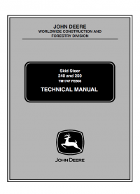
This Technical Manual is a comprehensive guide for repairing and servicing the John Deere 240 and 250 Skid Steer Loaders. It provides detailed service manuals, installation instructions, technical specifications, operating instructions, and troubleshooting procedures to help you maintain and repair your equipment effectively.
How This Manual Will Help You
Using this manual, you can:
- Perform Accurate Repairs: Follow step-by-step instructions to fix issues correctly.
- Troubleshoot Problems: Diagnose and resolve issues with detailed troubleshooting guides.
- Understand Technical Specifications: Access important data and specifications for your skid steer loaders.
- Maintain Equipment Properly: Follow maintenance procedures to keep your loaders in optimal condition.
- Improve Efficiency: Save time by having all necessary information in one comprehensive guide.
This technical manual includes:
- Service Manuals: Detailed instructions for servicing your equipment.
- Installation Instructions: Guidance on installing parts and components correctly.
- Technical Specifications: Comprehensive data on the loaders' systems and components.
- Operating Instructions: Information on how to operate your skid steer loaders safely and efficiently.
- Troubleshooting Guides: Procedures for diagnosing and resolving problems.
- Diagrams and Illustrations: Visual aids to support understanding and facilitate repairs.
This manual comes in PDF format with 506 printable pages. It's a high-quality, indexed file, allowing you to find the necessary information with just one click. We recommend using Adobe Acrobat Reader to ensure all images and graphics display correctly.
Models Covered
- John Deere 240 Skid Steer Loader
- John Deere 250 Skid Steer Loader
Manual Contents
The technical manual is organized into the following sections:
Safety
Specifications and Information
- Specifications
- Metric Fastener Torque Values
- Metric Fastener Torque Values—Grade 7
- Inch Fastener Torque Values
- O-Ring Seal Service Recommendations
- Diesel Fuel Specifications
- Engine Oil Specifications
- Chain Case Oil Specifications
- General Application Grease Specifications
- Coolant Specifications
- Serial Number Location
Diesel Engine
- Special or Essential Tools
- Sealant Application Guidelines
- Troubleshooting
- Diagnosis
- Tests and Adjustments
- Preliminary Engine Testing
- General Tune-Up Recommendations
- Test Thermostat Opening Temperature
- Check Engine Oil Pressure
- Measure Engine Blow-By
- Cylinder Compression Pressure Test
- Fuel Supply Pump Pressure
- Fast and Slow Idle Adjustment
- Fuel Injection Pump Timing Adjustment
- Check and Adjust Valve Clearance
- Repair
- Engine Repair Stand
- Mount Engine on Repair Stand
- Engine Removal/Installation
- Radiator Removal, Inspection, and Installation
- Clean Engine
- Engine Disassembly Sequence
- Engine Assembly Sequence
- Cylinder Head – Exploded View
- Check Valve Lift
- Remove Cylinder Head
- Clean Injection Nozzle Bores
- Valve Actuating Parts
- Remove Valves and Valve Springs
- Checking Cylinder Head Flatness
- Clean Valve Guides
- Measure Valve Guides
- Clean and Inspect Valve Seats
- Lapping Valve Seats
- Check Valve Recess
- Remove Valve Seat Inserts
- Valve Seat Insert Installation
- Inspect and Measure Valves
- Grind Valves
- Inspect and Measure Valve Springs
- Inspect Valve Rotators
- Install Valves
- Install Cylinder Head
- Torque Turn Tightening Method
- Checking Rocker Arm Shaft
- Install Rocker Arm Assembly
- Install Rocker Arm Cover
- Final Work
- Cylinder Block Exploded View
- Remove Pistons and Connecting Rods
- Measure Cylinder Liner Bore
- Remove Cylinder Liners
- Cylinder Liner Deglazing
- Cylinder Block Cleaning
- Check Piston Cooling Jets
- Cam Follower Bore Measure
- Measure Camshaft Bore
- Remove Camshaft Bushing
- Install Camshaft Bushing
- Measure Crankshaft Bore
- Replace Crankshaft Bearing Caps
- Cylinder Block Top Deck Flatness
- Measure Cylinder Liner Protrusion
- Liner Packing Installation
- Liner O-Ring Installation
- Install Cylinder Liners
- Measure Connecting Rod Bearing
- Rod Bearing Clearance
- Connecting Rod Bushing
- Replace Connecting Rod Bushing
- Measure Piston Pin
- Clean and Inspect Pistons
- Measure Piston Pin Bore
- Piston Top Ring Groove
- Piston Second and Third Ring Grooves
- Piston Head and Skirt Checking
- Install Piston Rings
- Piston Rings Staggering
- Piston/Liner Set Information
- Assemble Piston and Connecting Rod
- Install Piston and Connecting Rod
- Measure Piston Protrusion
- Complete Final Assembly
- Remove Crankshaft Pulley
- Install Crankshaft Pulley
- Flywheel Removal
- Flywheel Ring Gear Replacement
- Install Ball Bearing
- Install Flywheel
- Crankshaft Rear Oil Seal
- Flywheel Housing Replacement
- Measuring Crankshaft End Play
- Remove Crankshaft
- Crankshaft Inspection
- Measure Crankshaft Journal Diameter
- Determine Crankshaft Main Bearing Clearance
- Regrinding Crankshaft
- Crankshaft Regrinding Guidelines
- Micro-Finishing Specifications
- Replace Crankshaft Gear
- Install Main Bearing Inserts
- Install 2-Piece Thrust Bearing
- Install 6-Piece Thrust Bearing
- Crankshaft Installation
- Measure Timing Gear Backlash
- Remove Camshaft
- Measure Camshaft Journal
- Measure Height of Cam Lobe
- Replace Camshaft Gear
- Tachometer Pick-Up Pin Removal
- Install Camshaft
- Measure Cam Follower
- Measure Idler Gear End Play
- Remove Front Plate
- Idler Gear Bushing and Shaft Measure
- Idler Gear Bushing Replacement
- Remove Idler Shaft
- Install Idler Shaft Spring Pin
- Install Idler Shafts
- Install Front Plate
- Install Upper Timing Gear
- Install Lower Timing Gear
- Install Oil Deflector
- Install Timing Gear Cover
- Install Crankshaft Front Oil Seal
- Install Wear Ring
- Remove Oil Cooler
- Replace Oil Cooler Nipple
- Install Oil Cooler
- Remove Oil Pressure Regulating Valve
- Replace Oil Pressure Regulating Valve Seat
- Install Oil Pressure Regulating Valve
- Replace Oil Dipstick Guide Adapter
- Replace Oil Bypass Valve
- Replace Oil Pump Strainer
- Remove Oil Pump
- Gear Axial Clearance
- Gear Radial Clearance
- Oil Pump Specifications
- Oil Pump Installation
- Install Oil Pan
- Water Pump—Exploded View
- Remove Water Pump
- Disassemble Water Pump
- Assemble Water Pump
- Install Water Pump
- Remove/Install Thermostat
- Cold Start Advance Wire Harness (If Equipped)
- Cooling System Deaeration
- Check Fan/Alternator Belt Tension
- Install Fan
- Block Heater (Optional)
- Check Air Inlet Pipe
- Exhaust Manifold Inspection
- Remove Turbocharger
- Check Radial Bearing Clearance
- Check Axial Bearing End Play
- Repair Turbocharger
- Prelube Turbocharger
- Install Turbocharger
- Turbocharger Break-In
- Turbocharger Recommendations
- Replace Fuel/Water Separator Filter
- Replace Fuel Pump
- Remove Stanadyne DB4 Fuel Injection Pump
- Repair of Injection Pump
- Install Stanadyne DB4 Fuel Injection Pump
- Remove Fuel Injection Nozzle
- Clean Fuel Injection Nozzle
- Fuel Injection Nozzle Test
- Fuel Injection Nozzle Disassembly
- Adjust Fuel Injection Nozzle
- Install Fuel Injection Nozzle
- Bleed Fuel System
- Engine Break-In Instructions
- Engine Break-In Oil
- Using Stanadyne "Time-Trac" as Tachometer
- Turbocharger Operation
- Check Turbocharger Boost Pressure
- Diagnosing Turbocharger Malfunctions
- Fuel Injection Pump
- Cold Start Advance System Operation (If Equipped)
- Fuel Injection Nozzles—General Information
- Diagnosing Fuel System Malfunctions
- Testing Fuel Injection Nozzles on a Running Engine
- Specifications
- Cylinder Head and Valves Specifications
- Cylinder Block, Liners, Pistons, and Rods Specifications
- Crankshaft, Main Bearings, and Flywheel Specifications
- Camshaft and Timing Gear Train Specifications
- Lubrication System Specifications
- Cooling System Specifications
- Fuel System Specifications
- Engine System—Diagnosis and Tests Specifications
- Fuel System—Operation and Tests Specifications
- Capacities
Electrical
- Specifications
- Electrical Diagnostic Information
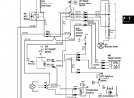
- Reading Electrical Schematics
- Theory of Operation Information
- Common Circuit Tests
- Wire Color Abbreviation Chart
- Legend for Electrical Components
- Component Location
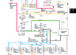
- Electrical Schematics
- Main Schematic
- Electrical Wire Harnesses
- Engine Wire Harness (W1)
- ROPS Wire Harness (W2)
- Dual Flasher Wire Harness (W3)
- Cold Start Wire Harness (W4)
- Cab Heater/Defroster Wire Harness (W5, W6, W7)
- Backup Alarm Wire Harness (W8)
- Wiper/Washer Wire Harness (W9)
- Troubleshooting Chart
- Theory of Operation and Diagnosis
- Power and Cranking Circuit Operation
- Power and Cranking Circuit Schematic
- Power and Cranking Circuit Diagnosis
- Power and Cranking Circuit Test Points
- Fuel and Preheat Circuit Operation
- Fuel and Preheat Circuit Schematic
- Fuel Circuit Diagnosis
- Fuel Circuit Test Points
- Preheat Circuit Diagnosis
- Preheat Circuit Test Points
- Charging Circuit Operation
- Charging Circuit Schematic
- Charging Circuit Diagnosis
- Charging Circuit Test Points
- Boom and Bucket Lockout and Park Brake Circuit Operation
- Boom and Bucket Lockout and Park Brake Circuit Schematic
- Boom and Bucket Lockout and Park Brake Circuit Diagnosis
- Boom and Bucket Lockout and Park Brake Circuit Test Points
- Gauges and Warning Lights Circuit Operation
- Gauges and Warning Lights Circuit Schematic
- Seat Belt Warning Light Circuit Diagnosis
- Seat Belt Warning Light Circuit Test Points
- Park Brake Switch and Warning Light Circuit Diagnosis
- Park Brake Switch and Warning Light Circuit Test Points
- Air Filter Restriction Warning Light Circuit Diagnosis
- Air Filter Restriction Warning Light Circuit Test Points
- Hydraulic Oil Overtemperature Warning Light Circuit Diagnosis
- Hydraulic Oil Overtemperature Warning Light Circuit Test Points
- Hydraulic Filter Restriction Warning Light Circuit Diagnosis
- Hydraulic Filter Restriction Warning Light Circuit Test Points
- Fuel Gauge Circuit Diagnosis
- Fuel Gauge Circuit Test Points
- Engine Overtemperature Warning Light Circuit Diagnosis
- Engine Overtemperature Warning Light Circuit Test Points
- Coolant Temperature Gauge Circuit Diagnosis
- Coolant Temperature Gauge Circuit Test Points
- Engine Oil Pressure Warning Light Circuit Diagnosis
- Engine Oil Pressure Warning Light Circuit Test Points
- Engine Oil Pressure Gauge Circuit Diagnosis
- Engine Oil Pressure Gauge Circuit Test Points
- High-Flow Circuit (Optional) Operation
- High-Flow Circuit Schematic
- High-Flow Circuit Diagnosis
- High-Flow Circuit Test Points
- Lights Circuit Operation
- Lights Circuit Schematic
- Lights Circuit Diagnosis
- Light Circuit Test Points
- Dual Flasher Circuit (Optional) Operation
- Dual Flasher Circuit Schematic
- Dual Flasher Circuit Diagnosis
- Dual Flasher Circuit Test Points
- Cab Heater/Defroster Circuit (Optional) Operation
- Cab Heater/Defroster Circuit Schematic
- Cab Heater/Defroster Circuit Diagnosis
- Cab Heater/Defroster Circuit Test Points
- Backup Alarm Circuit (Optional) Operation
- Backup Alarm Circuit Schematic
- Backup Alarm Circuit Diagnosis
- Backup Alarm Circuit Test Points
- Wiper/Washer Circuit (Optional) Operation
- Wiper/Washer Circuit Schematic
- Wiper/Washer Circuit Diagnosis
- Wiper/Washer Circuit Test Points
- Tests and Adjustments
- Battery Test
- Charge Battery
- Battery Load Test
- Regulated Amperage and Voltage Test
- Starting Motor Loaded Amperage Draw Test
- Starting Motor No-Load Amperage and RPM Tests
- Starting Motor Solenoid Test
- Air Filter Restriction Switch Test
- Engine Coolant Temperature Sender/Switch Test
- Cold Weather Start Switch Test (Model 250 Only)
- Engine Oil Pressure Switch/Sender Test
- Manifold Preheater Test
- Manifold Preheater Relay Test
- Key Switch Test
- Park Brake Switch Test
- Pre-Heater Switch Test
- Light Switch Test
- Cab Door Switch Test
- Dual Flasher Switch Test
- High-Flow Switch Test
- Blower Switch Test
- Wiper/Washer Switch Test
- Fuel Level Sender Test
- Seat Safety Switch Test
- Seat Belt Switch Test
- Hydraulic Oil Overtemperature Switch Test
- Park Brake Solenoid Test
- Boom Lockout Solenoid Test
- Bucket Lockout Solenoid Test
- Hydraulic Oil Filter Restriction Switch Test
- Component Replacement
- Air Filter Restriction Switch
- Coolant Temperature Sender/Switch
- Cold Weather Start Switch (Model 250 Only)
- Engine Oil Pressure Switch/Sender
- Manifold Preheater
- Manifold Preheat Relay
- Instrument Panel Component Location
- Key Switch
- Instrument Panel Switches
- Cab Heater Thermostat (If Equipped)
- Instrument Cluster
- Fuel Level Sender
- Seat Safety Switch
- Seat Belt Switch
- Starter
- Alternator
- Hydraulic Oil Overtemperature Switch
- Park Brake Solenoid
- Hydraulic Oil Filter Restriction Switch
- Backup Alarm (Optional)
- Alarm
- Switch
Power Train (Chaincase and Axles)
- Specifications
- Other Materials
- Special Tools
- Troubleshooting
- Diagnosis
- Repair
- Chain Case Oil Level Check
- Chain Case Access Plate
- Drive Chain Tension Adjustment
- Axle Housing Removal/Installation
- Axle Housing Disassembly/Assembly
- Drive Chain and Sprocket Removal/Installation
- Power Train Component Location
- Operation
- Hydrostatic Power Train
Hydrostatic Power Train
- Specifications
- Tests and Adjustments Specifications
- Service Parts Kits
- Torque Specifications
- Repair Specifications
- Special or Essential Tools
- Other Materials
- Hydrostatic System Operation
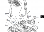
- Hydrostatic Component Location
- Hydrostatic System Schematic
- Troubleshooting
- Diagnosis
- Tests and Adjustments
- Hydraulic/Charge Pump Pressure Test
- Hydraulic/Charge Pump Flow Test
- Hydrostatic Pump High Pressure Relief Test
- Wheel Speed Test
- Hydrostatic Pump Flow Test
- Hydrostatic Pump Case Drain Test
- Hydrostatic Case Drain Pressure Test
- Repair
- Start-Up Procedure After Component Replacement
- Hydrostatic Pump Removal
- Front Hydrostatic Pump Exploded View
- Center Manifold Exploded View (Early Models)
- Center Manifold Exploded View (Late and Converted Models)
- Rear Hydrostatic Pump Exploded View
- Hydrostatic Pump Disassembly
- Hydrostatic Pump Inspection
- Hydrostatic Pump Assembly
- Hydrostatic Pump Installation
- Hydrostatic Motor Removal/Installation
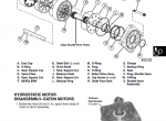
- Hydrostatic Motor Exploded View
- Hydrostatic Motor Disassembly
- Hydrostatic Motor Inspection
- Hydrostatic Motor Assembly
Steering
- Theory of Operation
- Troubleshooting
- Tests and Adjustments
- Centering Plate Adjustment—Single Plate Models
- Centering Plate Adjustment—Dual Plate Models
- Steering Control Lever Adjustment—Centering
- Steering Detent Adjustment - Dual Plate Models
- Steering Control Lever Stops Adjustment—Tracking
- Auxiliary Hydraulic Control Handle Adjustment
- Hydraulic Control Handle Adjustment – Hands Only Machines
- Repair
- Centering Plate Removal—Single Plate Models
- Centering Plate Removal—Dual Plate Models
- Centering Plate Inspection
- Centering Plate Installation—Single Plate Models
- Centering Plate Installation—Dual Plate Models
- Steering Dampener Removal/Inspection/Installation
- Steering Control Lever Removal/Inspection/Installation
- Steering Cross Shaft Assembly Removal/Installation—Single Plate Models
- Steering Cross Shaft Assembly Removal/Installation—Dual Plate Models
- Steering Cross Shaft Assembly Repair—Dual Plate Models
- Steering Control Lever Handle Disassembly/Assembly
- Steering Component Location—Single Plate Models
- Steering Component Location—Dual Plate Models
- Diagnostics
- Specifications
- Tests and Adjustments Specifications
- Torque Specifications
- Special or Essential Tools
Brakes
- Specifications
- Other Materials
- Theory of Operation
- Brake Exploded View
- Diagnosis and Troubleshooting
- Diagnosis
- Troubleshooting
- Repair
- Brake Removal
- Brake Disassembly
- Brake Inspection
- Brake Assembly
- Brake Installation
- Burnish Brakes
- Brake Actuator Cylinder Removal/Installation
Hydraulics
- Tests and Adjustments
- Boom and Bucket Lockout Solenoids Check
- System Relief Valve Pressure Test
- Hydraulic/Charge Pump Pressure Test
- Hydraulic/Charge Pump Flow Test
- Circuit Relief Valve Test
- Boom Drift Down Check
- Boom Lift Check Test
- Boom Drift Up Check
- Bucket Drift Dump Position Check
- Bucket Drift Rollback Position Check
- Bucket Lift Check Test
- Bucket Self-Leveling Adjustment
- Repair
- Hydraulic/Charge Pump Removal
- Hydraulic/Charge Pump Disassembly
- Hydraulic/Charge Pump Component Inspection
- Hydraulic/Charge Pump Assembly
- Hydraulic/Charge Pump Installation
- High-Flow Pump
- High-Flow Valve
- Control Valve Removal
- Control Valve Disassembly
- Control Valve Inspection
- Control Valve Cross Section
- Control Valve Assembly
- Control Valve Installation
- Self-Leveling Valve
- Boom Cylinder Removal
- Boom Cylinder Installation
- Bucket Cylinder Removal
- Bucket Cylinder Installation
- Boom and Bucket Cylinder Repair
- System Components and Operation
- System Schematic
- Specifications
- Torque Specifications
- Other Materials
- Service Parts Kits
- Bucket Cylinder Component Location
- Boom Cylinder Component Location
- Troubleshooting
- Diagnosis
- System Component Location
- Control Valve Component Location
- Hydraulic/Charge Pump Component Location
- System Schematic
- System Component Location
Miscellaneous
- Specifications
- Torque Specifications
- Other Materials
- Special or Essential Tools
- Repair
- Raising ROPS (Rollover Protection Structure)
- Boom Lock Removal/Installation
- Raising and Blocking Skid Steer
- Cover Plate Removal/Installation
- Using Remote Start Box
- ROPS Removal/Installation
- Boom
- Lower Boom Link Removal/Installation
- Upper Boom Link Removal/Installation
- Quik-Tatch® Hitch Coupling Removal/Installation
- Quik-Tatch® Repair
- Boom Removal/Installation
- Cab Heater/Defroster (Optional)
- Filter Replacement
- Heater Core Removal/Installation
- Blower Removal/Installation
- Control Valve Removal/Installation
- Cab Heater Deaeration
- Cab Door (If Equipped)
- Windshield Wiper/Washer (Optional)
- Wiper Motor
- Washer Pump
Easy Purchase and Access
Ordering this manual is simple. Click the 'Buy Now' button, and you'll receive an email with download instructions and recommendations for use. The manual is user-friendly, even for those who are not experienced with computers.
If you have any questions or need assistance, please feel free to contact our support team. We're here to help.

![repair manual John Deere Service Advisor AG & CF 5.4.44 [06.2025] Technical manuals & Diagnostic Software](/imgs/type_instr.gif)
![repair manual John Deere Service Advisor AG & CF 5.4.44 [06.2025] Technical manuals & Diagnostic Software](https://www.epcatalogs.com/file/base/7wCEvBLSdZwzQlQnrx3OWQi2kgNbbgYop7dTciHgkkCE6obhMi6hyZvEHYYAJhCi/john-deere-service-advisor-ag-cf-5-3-225-05-2024.png)

