This service manual is intended for serve, repair and maintenance JCB Teletruks following models: 525-58, 525-67, 525-58, 525-67, 530-95, 530-110, 530-120, 530-67, 537-120, 537-130.
This manual covers knowledge of workshop practice, safety procedures, and general techniques associated with the routine maintenance and current repair of JCB Teletruks.
This pdf service manual explains the correct operation, maintenance of the equipment, as well as routine repair and maintenance procedures, and other repair information. It contains important service information for the care and safety operation of Teletruks of this brand.
Subject to the careful observance of the maintenance instruction contained in this manual, you can avoid often unnecessary breakdowns and injuries, thereby ensuring a long and reliable operation of the loader.
This service repair manual is a PDF file. You can preview this manual by clicking on the link 'JCB pdf manual instant preview'. This link is located in front of the service workshop manual description.
You can work with this PDF instruction using applications that support PDF files. We recommend using Adobe PDF Reader to ensure that all pages and pictures are read and opened normally.
Publication No. 9803/3600
Models covered:
525-58 and 525-58 Farm Special - from machine Serial Number 561001
525-67 and 525-67 Farm Special - from machine Serial Number 561001
525-58 and 525-67 Farm Special Plus
525-58 and 525-67 Basic Servo Options
527-58 and 527-67 - from machine Serial Number 572775
530-95 - from machine Serial Number 564980
530-110 - from machine Serial Number 563359
530-110 and 530-120 - PlaceAce
530-110 and 530-120 Servo Options
530-120 - from machine Serial Number 562601
530-67 and 530-67 Farm Special - from machine Serial Number 571001
535-67 - from machine Serial Number 572775
537-120 and 537-130 from machine Serial Number 572900
Note: Information covers two-stage and three-stage boom machines.
Contents:
- Section 1 - General
- Fluids, Lubricants, Capacities & Specifications
- Service Schedules
- Greasing
- Oiling
- Boom Safety Strut
- Section 2 - Hydraulics
- Technical Data
- General Description
- Hydraulic Fluid Level & Filter
- Draining Fluid & Cleaning Suction Strainers
- Hydraulic Tank Removal & Replacement
- Pump Operation
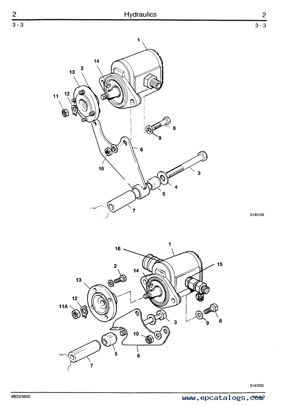
- Pump Removal & Replacement
- Pump Dismantle & Assembly
- Supplementary Pump (Farm Special Plus, 530-67, 535-67)
- Machine Neutral Circuit (without torsion box cooling)
- Machine Neutral Circuit (with torsion box cooling)
- Machine Neutral Circuit (with filter in steer circuit)
- Machine Neutral Circuit (with supplementary pump)
- Machine Neutral Circuit (with priority steer/fan pump)
- Control Valve Block Neutral Circuit
- Boom Lift Operation (525-67, 527-67, 530-67, & 535-67)
- Boom Lower Operation (525-67, 527-67, 530-67, & 535-67)
- Boom Lift Operation (525-58, 527-58)
- Boom Lower Operation (525-58, 527-58)
- Hose Burst Operation
- Boom Extend/Retract Operation
- Sway Operation
- Boom Lift Operation (530-110/120, 537-120/130)
- Boom Lower Operation (530-110/120, 537-120/130)
- Boom Extend Regenerative (530-110/120, 537-120/130)
- Boom Extend High Pressure (530-110/120, 537-120/130)
- Boom Retract (530-110/120, 537-120/130)
- Stabiliser Check Valve Operation
- Stabiliser Operation
- M.R.V. Operation
- A.R.V. Operation
- Control Valve Block Removal & Replacement
- Control Valve Block Dismantle & Assembly
- Dual Function Controls Assembly
- Pressure Testing
- Lift Rams Removal & Replacement
- Displacement Rams Removal & Replacement
- Extension Ram Removal & Replacement (525-58, 527-58)
- Extension Ram Removal & Replacement
- Tilt Ram Removal & Replacement
- Sway Ram Removal & Replacement
- Tow Hitch Ram Removal & Replacement
- Inner Extension Ram Removal & Replacement
- Outer Extension Ram Removal & Replacement
- Boom Extension Circuit Bleeding Procedure
- Extension Ram Make Up Valve
- Boom Hoses Removal & Replacement (530-95)
- Boom Hoses Chain Track
- Extension Ram Removal & Replacement (530-95)
- Stabiliser Ram Removal & Replacement
- Diverter Valve Removal & Replacement
- Diverter Valve Dismantle & Assembly
- Typical Ram Dismantle & Assembly
- Tow Hitch Ram Dismantle & Assembly
- Typical Ram with Dowel Head Dismantle & Assembly
- Fan Motor Removal, Replacement & Adjustment
- Fan Motor (Sundstrand) Dismantle & Assembly
- Fan Motor (Ultra) Dismantle & Assembly
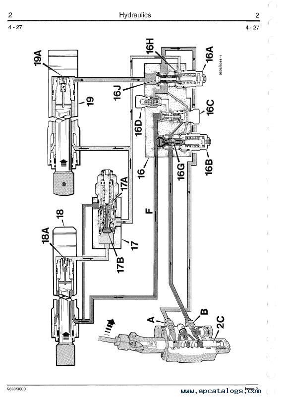
- Schematic Hydraulic Circuit
- Section 3 - Body and Framework
- Boom Shimming - Typical Method
- Boom Shimming - 525-58/67, 527-58/67, 530-67, 535-67
- Boom Shimming - 530-95
- Boom Shimming - 530-110
- Boom Wear Pads Shimming - 530-120, 537-120/130
- Inner Extension Ram Wear Pads - 530-120 & 530-95
- Inner Boom Removal & Replacement
- Boom Removal & Replacement
- Cab Removal & Replacement
- Front Windscreen Removal & Replacement
- Rear Window Removal & Replacement
- Side Window Removal & Replacement
- Rear Window Hinged
- Q - Fit Carriage Removal & Replacement
- Fuel Tank Removal & Replacement
- Air Conditioning Option
- Section 4 - Loadall PlaceAce Control System
- Technical Data
- Control System Description
- Valve Block Operation
- Pulsar Description & Operation
- Valve Block Removal & Replacement
- Pulsar Solenoid Removal & Replacement
- Main Spool Removal & Replacement
- Boom Angle Sensor Removal & Replacement
- Boom Extension Sensor Removal & Replacement
- Attitude Sensor Removal & Replacement
- Motion Pac Control Unit Removal & Replacement
- Driver Cards Removal & Replacement
- Display Unit Removal & Replacement
- Joystick Removal & Replacement
- Lever Control (Stabilisers) Removal & Replacement
- Control Valve Dismantle & Assembly
- Valve Stack Dismantle & Assembly
- Pressure Testing
- Full System Calibration
- Vehicle Attitude & Tachometer Signal Calibration
- Pulsar Solenoid Calibration
- Driver Card Calibration/Adjustment
- Functional Checks
- Fault Finding
- Schematic Hydraulic Circuit 530-110/120
- Schematic Electrical Circuit 530-110/120
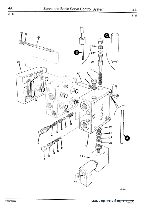
- Section 4A - Servo Control System
- Technical Data
- Servo Control System Description
- Basic Servo Control System Description
- Valve Block Operation
- Valve Block Main Spool Operation
- Joystick Control Lever Operation
- Cab & Chassis Electrical Circuits Description
- Valve Block Removal & Replacement
- Control Valve Section Dismantle & Assembly
- Control Valve Inlet & Outlet Dismantle & Assembly
- Joystick Removal & Replacement
- Lever Control Removal & Replacement
- Pressure Testing
- Bench Testing Joystick Control Levers
- Bench Testing Sway/Stabiliser Control Levers
- Fault Finding
- Schematic Hydraulic Circuit
- up to machine s/n 574295
- Schematic Electrical Circuit
- Section 5 - Engine
- Technical Data
- General Description
- Engine Cover
- Engine Oil Filter
- Fuel Filter
- Fuel Pump
- Bleeding
- Cooling System
- Alternator Drive Belt
- Pre-Cleaner
- Air Filter
- Radiator
- Engine Removal & Replacement
- Exhauster Removal & Replacement
- Turbo Charger Engine Insulation
- Naturally Aspirated Engine Insulation
- Section 6 - Transmission
- Syncro Shuttle Technical Data
- Syncro Shuttle General Description
- Powershift Technical Data
- Recovery Procedure
- Checking & Changing Oil
- Syncro Shuttle General Description & Operation
- Syncro Shuttle Operation
- Syncromesh Description
- Four Wheel Drive Clutch Operstion (4 wheel drive)
- Four Wheel Drive Clutch Operstion (2 wheel drive)
- Powershift General Description
- Powershift Operation
- Powershift Drive Paths
- Syncro Shuttle Fault Finding
- Powershift Fault Finding
- Transmission Removal & Replacement
- Torque Converter Removal & Replacement
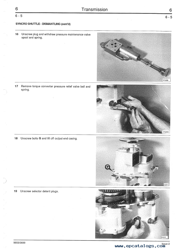
- Syncro Shuttle Dismantling
- Solenoid Valve Dismantling & Assembly
- Reverser Unit Dismantling
- Reverser Unit Assembly
- Reverser Unit (Later Type) Dismantling
- Reverser Unit (Later Type) Assembly
- Mechanical 4 Wheel Drive Dismantling
- Mechanical 4 Wheel Drive Assemmbly
- Hydraulic 4 Wheel Drive Dismantling
- Hydraulic 4 Wheel Drive Assembly
- Hydraulic 2/4 Wheel Drive IP 67 Machines
- Pressure Testing 2/4WD Clutch
- 2/4WD Clutch Fault Finding
- Torque Converter Stall Test
- Piston Ring Seal Fitting Procedure
- Propshafts
- Powershift
- Section 7 - Axles
- Technical Data
- Road Wheel Removal & Replacement
- Front Axle Breather Removal & Replacement
- Axle Oil Level
- Cutaway of Front Axle
- Cutaway of Rear Axle
- Front Axle (Fixed)
- Front Axle (Sway)
- Rear Axle
- Rear Axle 537-120/130
- Hub (Dowel) & Driveshaft Dismantling
- Hub (Dowel) & Driveshaft Assembly
- Front Hub (Splined) & Driveshaft Dismantling
- Front Hub (Splined) & Driveshaft Assembly
- Rear Hub (Splined), Brakes & Driveshaft Dismantling
- Rear Hub (Splined), Brakes & Driveshaft Assembly
- Brakes Dismantling
- Brakes Assembly
- Front Drive Head Dismantling
- Front Drive Head Assembly
- Renewing Axle Pinion Oil Seal
- Rear Drive Head Dismantling
- Rear Drive Head Assembly
- Limited Slip Differential Dismantle & Assembly
- Section 8 - Brakes
- Technical Data
- Parking Brake Adjusting & Testing
- Parking Brake Dismantling & Assembly
- Parking Brake - 530-110 Machines (From TBA)
- Brake Caliper - 530-110 Machines (From TBA)
- Brake System Bleeding (Front Axle)
- Brake System Bleeding (Rear Axle)
- Single Master Cylinder Without Servo
- Single Master Cylinder With Servo
- Tandem Master Cylinder With Servo
- Single Master Cylinder Without Servo
- Single Master Cylinder With Servo
- Tandem Master Cylinder With Servo
- Section 9 - Hydraulic Steering
- Technical Data
- General Description
- Flow Regulating Valve Operation
- Tandem Steering/Fan Pump Dismantling & Assembly
- Steering/Fan Pump Removal & Replacement
- Single Steering/Fan Pump Dismantling & Assembly
- System Operation (Machines Without IP67 Electrics)
- System Operation (Machines With IP67 Electrics)
- Steering Description
- Steering Shock Valve Description
- Priority Valve Description
- Steering Unit Removal & Replacement
- Steering Unit Dismantling & Assembly
- Steering Mode Valve Removal & Replacement
- Steering Mode Valve Dismantling & Assembly
- Steering Ram Removal & Replacement
- Steering Ram Dismantling & Assembly
- Bleeding
- Pressure Testing
- Section 10 - Electrics
- Introduction
- Technical Data
- Fuses
- Relay Location
- Test Methods
- Batteries Testing
- Alternator
- Starting Circuit Test
- Starter Motor
- Safe Load Indicator Adjustment
- Instruction for use of the SLI Test Box
- Safe Load Indicator Testing
- Safe Load Indicator Testing from serial No. 576404
- Harness Repair
- Wiring Diagram
- Section 11 - Service Tools
- Numerical List
- Section List
- Section List
- Section List
- Sealing and Retaining Compounds
Our company provides for sale original spare part catalogs, workshop manuals, diagnostic software for all models of engines, cars, trucks, buses, forklifts, tractors, harvesters, cranes, buldozers, generators, construction and agricultural machines, motorcycles. To purchase a catalog online, please add the product to your cart, fill in the contact form online. Our managers proceed your order the same day.


![spare parts catalog CLAAS Parts Doc Offline Update v919 [02.2026]](/imgs/type_zapch.gif)


