This service manual is a collection of all the important service information, recommendations, professional tips, cautions and rules for using the JCB Teletruks 500 Series. Its timely reading can prevent neglect of the technique and its misuse. Also, this manual covers the current repair and routine maintenance instruction, care, and safety information, lots of pictures and illustrations, other repair information.
For convenience this pdf service manual is compiled in sections, e.g. "Hydraulics", "Electrics", etc. In order to find details of a specific component, reference should be made to the alphabetical index at the back of the book.
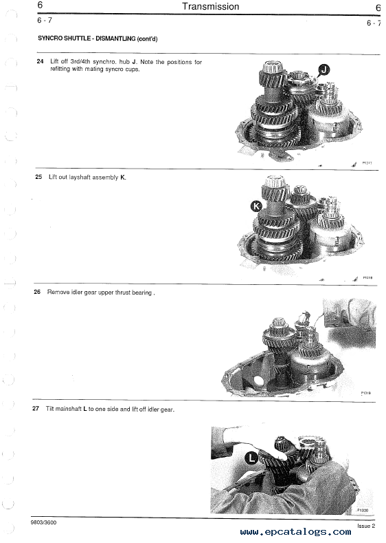
Illustrations that show a dismantled component are numbered as a guide to the dismantling sequence, which generally can be reversed for assembly.
You can study this service repair manual using screenshots and a list of content, which is presented in the manual description. You can also follow the link 'JCB pdf manual instant preview', and preview the pages of this manual.
Buying this service workshop manual is very simple and fast: you need to click on the 'Buy Now' button and follow the further instructions. After payment of the pdf instruction, you will receive a download link. You are downloading a PDF document that works with applications such as Adobe Acrobat Reader, Foxit Reader, etc. For your convenience, you can print the manual, use it as a service handbook and store it directly near the equipment.
Publication No. 9803-3600U
This manual covers the following machines:
505-19 - Serial Number 561001 - 579365
505-22 - Serial Number 561001 - 579365
508-40 - Serial Number 562601 - 579365
506-36 - Serial Number 563359 - 579999
510-40 - Serial Number 564542 - 579365
508-40, 508-40 - PlaceAce
505-19, 505-22 - Basic Servo Options
506-36, 508-40 - Servo Options
506B - Serial Number 570000 - 579766
Note: Information covers two-stage and three-stage boom machines.
From m/c No. 561001
Contents:
- Section 1 - General
- Fluids, Lubricants, Capacities & Specifications
- Service Schedules
- Greasing
- Oiling
- Boom Safety Strut
- Section 2 - Hydraulics
- Technical Data
- General Description
- Hydraulic Fluid Level & Filter
- Draining Fluid & Cleaning Suction Strainers
- Hydraulic Tank Removal & Replacement
- Pump Operation
- Pump Removal & Replacement
- Pump Dismantle & Assembly
- Control Valve Block Removal & Replacement
- Control Valve Block Dismantle & Assembly
- Dual Function Controls Assembly
- Pressure Testing
- Lift Rams Removal & Replacement
- Displacement Rams Removal & Replacement
- Extension Cylinder Removal & Replacement (505-19)
- Extension Cylinder Removal & Replacement (505-22)
- Tilt Cylinder Removal & Replacement
- Sway Cylinder Removal & Replacement
- Tow Hitch Cylinder Removal & Replacement
- Inner Extension Cylinder Removal & Replacement
- Outer Extension Cylinder Removal & Replacement
- Stabilizer Cylinder Removal & Replacement
- Boom Extension Circuit Bleeding Procedure
- Extension Cylinder Make Up Valve
- Diverter Valve Removal & Replacement
- Diverter Valve Dismantle & Assembly
- Hose Burst Protection Valve (506B)
- Removal, Replacement, Dismantle & Assembly
- Typical Cylinder Dismantle & Assembly
- Tow Hitch Cylinder Dismantle & Assembly
- Typical Cylinder with Dowel Head Dismantle & Assembly
- Fan Motor Removal, Replacement & Adjustment
- Fan Motor (Sundstrand) Dismantle & Assembly
- Fan Motor (Ultra) Dismantle & Assembly
- Schematic Hydraulic Circuit
- Section 3 - Body and Framework
- Boom Shimming - Typical Method
- Boom Shimming - 505-19/22
- Boom Shimming - 506-36
- Boom Shimming - 508-40, 510-40
- Boom Shimming - 506B
- Inner Extension Ram Wear Pads - 508-40, 510-40
- Inner Boom Removal & Replacement
- Boom Removal & Replacement
- Boom Extend Chain Removal & Replacement 506B
- Boom Retract Chain Removal & Replacement 506B
- Boom Chains Adjustment 506B
- Boom Chains Inspection 506B
- Cab Removal & Replacement
- Front Windsheid Removal & Replacement
- Rear Window Removal & Replacement
- Side Window Removal & Replacement
- Rear Window Hinged
- Q - Fit Carriage Removal & Replacement
- Fuel Tank Removal & Replacement
- Air Conditioning Option
- Section 4 - Loadall PlaceAce Control System
- Technical Data
- Control System Description
- Valve Block Operation
- Pulsar Description & Operation
- Valve Block Removal & Replacement
- Pulsar Solenoid Removal & Replacement
- Main Spool Removal & Replacement
- Boom Angle Sensor Removal & Replacement
- Boom Extension Sensor Removal & Replacement
- Attitude Sensor Removal & Replacement
- Motion Pac Control Unit Removal & Replacement
- Driver Cards Removal & Replacement
- Display Unit Removal & Replacement
- Joystick Removal & Replacement
- Lever Control (Stabilisers) Removal & Replacement
- Control Valve Dismantle & Assembly
- Valve Stack Dismantle & Assembly
- Pressure Testing
- Full System Calibration
- Vehicle Attitude & Tachometer Signal Calibration
- Pulsar Solenoid Calibration
- Driver Card Calibration/Adjustment
- Functional Checks
- Fault Finding
- Schematic Hydraulic Circuit 508-40, 510-40
- Schematic Electrical Circuit 508-40, 510-40
- Section 4A - Servo Control System
- Technical Data
- Basic Servo Control System Description
- Servo Control System Description
- Valve Block Operation
- Valve Block Main Spool Operation
- Joystick Control Lever Operation
- Cab & Chassis Electrical Circuits Description
- Valve Block Removal & Replacement
- Control Valve Section Dismantle & Assembly
- Control Valve Inlet & Outlet Dismantle & Assembly
- Joystick Removal & Replacement
- Lever Control Removal & Replacement
- Pressure Testing
- Bench Testing Joystick Control Levers
- Bench Testing Sway/Stabilizer Control Levers
- Fault Finding
- Schematic Hydraulic Circuit
- Schematic Electrical Circuit
- Section 5 - Engine
- Technical Data
- General Description
- Engine Cover
- Engine Oil Filter
- Fuel Filter
- Fuel Pump
- Bleeding
- Cooling System
- Alternator Drive Belt
- Pre-Cleaner
- Air Filter
- Radiator
- Engine Removal & Replacement
- Exhauster Removal & Replacement
- Turbo Charger Engine Insulation
- Naturally Aspirated Engine Insulation
- Section 6 - Transmission
- Syncro Shuttle Technical Data
- Syncro Shuttle General Description
- Powershift Technical Data
- Recovery Procedure
- Checking & Changing Oil
- Syncro Shuttle General Description & Operation
- Syncro Shuttle Operation
- Syncromesh Description
- Four Wheel Drive Clutch Operation (4 wheel drive)
- Four Wheel Drive Clutch Operation (2 wheel drive)
- Powershift General Description
- Powershift Operation
- Powershift Drive Paths
- Syncro Shuttle Fault Finding
- Powershift Fault Finding
- Transmission Removal & Replacement
- Torque Converter Removal & Replacement
- Syncro Shuttle Dismantling
- Syncro Shuttle Assembly
- Solenoid Valve Dismantling & Assembly
- Reverser Unit Dismantling
- Reverser Unit Assembly
- Reverser Unit (Later Type) Dismantling
- Reverser Unit (Later Type) Assembly
- Mechanical 4 Wheel Drive Dismantling
- Mechanical 4 Wheel Drive Assembly
- Hydraulic 4 Wheel Drive Dismantling
- Hydraulic 4 Wheel Drive Assembly
- Hydraulic 2/4 Wheel Drive IP 67 Machines
- Pressure Testing 2/4WD Clutch
- 2/4WD Clutch Fault Finding
- Torque Converter Stall Test
- Piston Ring Seal Fitting Procedure
- * Propshafts
- Powershift
- Section 7 - Axles
- Technical Data
- Road Wheel Removal & Replacement
- Water Ballast Tires
- Front Axle Breather Removal & Replacement
- Axle Oil Level
- Cutaway of Front Axle
- Cutaway of Rear Axle
- Front Axle (Fixed)
- Front Axle (Sway)
- Rear Axle
- Hub (Dowel) & Driveshaft Dismantling
- Hub (Dowel) & Driveshaft Assembly
- Front Hub (Splined) & Driveshaft Dismantling
- Front Hub (Splined) & Driveshaft Assembly
- Rear Hub (Splined), Brakes & Driveshaft Dismantling
- Rear Hub (Splined), Brakes & Driveshaft Assembly
- Brakes Dismantling
- Brakes Assembly
- Front Drive Head Dismantling
- Front Drive Head Assembly
- Renewing Axle Pinion Oil Seal
- Rear Drive Head Dismantling
- Rear Drive Head Assembly
- Limited Slip Differential Dismantle & Assembly
- Section 8 - Brakes
- Technical Data
- Parking Brake Adjusting & Testing
- Parking Brake Dismantling & Assembly
- Brake System Bleeding (Front Axle)
- Brake System Bleeding (Rear Axle)
- Single Master Cylinder Without Servo
- Single Master Cylinder With Servo
- Tandem Master Cylinder With Servo
- Single Master Cylinder Without Servo
- Single Master Cylinder With Servo
- Tandem Master Cylinder With Servo
- Section 9 - Hydraulic Steering
- Technical Data
- General Description
- Flow Regulating Valve Operation
- Tandem Steering/Fan Pump Dismantling & Assembly
- Steering/Fan Pump Removal & Replacement
- Single Steering/Fan Pump Dismantling & Assembly
- System Operation (Machines Without IP67 Electrics)
- System Operation (Machines With IP67 Electrics)
- Steering Description
- Steering Shock Valve Description
- Priority Valve Description
- Steering Unit Removal & Replacement
- Steering Unit Dismantling & Assembly
- Steering Mode Valve Removal & Replacement
- Steering Mode Valve Dismantling & Assembly
- Steering Ram Removal & Replacement
- Steering Ram Dismantling & Assembly
- Bleeding
- Pressure Testing
- Section 10 - Electrics
- Introduction
- Technical Data
- Fuses
- Relay Location
- Test Methods
- Batteries Testing
- Alternator
- Starting Circuit Test
- Starter Motor
- Fault Finding
- Harness Repair
- Wiring Diagram
- Section 11 - Service Tools
- Numerical List
- Section List
- Section List
- Section List
- Sealing and Retaining Compounds
- Section 12 - Boom Float, Return to Dig Option
- Numerical List
- Description
- Schematic Hydraulic Circuit
- Wiring Diagram
- Relay Location
- Fault Finding
- Micro Switch Adjustment
- Proximity Switch Adjustment
- Hose Burst Solenoid
- Displacement Isolation Valve & Pressure Switch
Our company provides for sale original spare part catalogs, workshop manuals, diagnostic software for all models of engines, cars, trucks, buses, forklifts, tractors, harvesters, cranes, buldozers, generators, construction and agricultural machines, motorcycles. To purchase a catalog online, please add the product to your cart, fill in the contact form online. Our managers proceed your order the same day.


![spare parts catalog CLAAS Parts Doc Offline Update v919 [02.2026]](/imgs/type_zapch.gif)


