This troubleshooting and repair manual provides detailed instructions for troubleshooting and repairing this Cummins engines (ISB, QSB5.9) in the chassis. Component and assembly rebuild procedures are provided in the engine shop manual.
This repair manual is organized to guide a service technician through the logical steps of identifying and correcting problems related to the engine. This manual does not cover vehicle or equipment problems.
This troubleshooting manual is intended to aid in determining the cause of engine-related problems and to provide recommended repair procedures.
This workshop manual comes in PDF format and works with any PDF Reader. The service manual is divided into sections by system. Each section provides general repair information, specifications, diagrams, and service tools where applicable, and other service information.
This manual is intended for these regions: USA, Canada, Australia, New Zealand, Puerto Rico.
Bulletin No. 3666193-01
Models:
ISB and QSB5.9 Engines
Contents:
- Section I - Introduction
- About This Manual
- Acronyms and Abbreviations
- General Cleaning Instructions
- General Repair Instructions
- General Safety Instructions
- How to Use the Manual
- Illustrations
- Symbols
- Section E - Engine Identification
- Engine Diagrams
- Engine Identification
- Specifications
- Section TS - Troubleshooting Symptoms
- Troubleshooting Procedures and Techniques
- Troubleshooting Symptoms Charts
- Section 0 - Complete Engine - Group 00
- Complete Engine - General Information
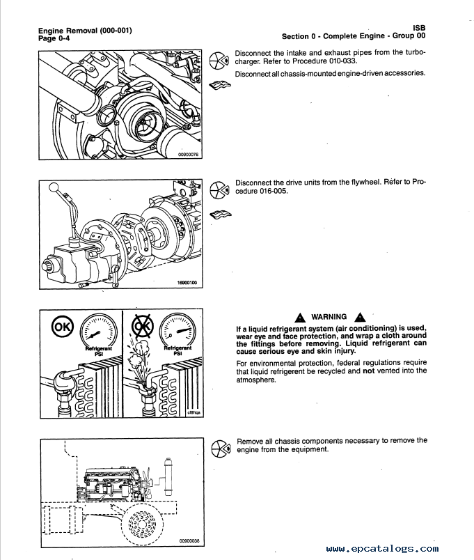
- Engine Installation
- Engine Mounting Bolts
- Engine Painting
- Engine Removal
- Service Tools
- Section 1 - Cylinder Block - Group 01
- Bearings, Connecting Rod
- Bearings, Main
- Camshaft
- Camshaft Bushings
- Camshaft Gear (Camshaft Removal)
- Connecting Rod
- Crankshaft
- Crankshaft Gear, Front (Crankshaft Installed)
- Crankshaft Gear, Front (Crankshaft Removed)
- Crankshaft Seal, Front
- Crankshaft Seal, Rear
- Crankshaft Speed Indicator Ring
- Crankshaft Wear Sleeve, Front
- Crankshaft Wear Sleeve, Rear
- Cylinder Block
- Gear Cover, Front
- Gear Housing, Front
- Piston
- Piston and Connecting Rod Assembly
- Piston Rings
- Service Tools
- Vibration Damper
- Vibration Damper, Rubber
- Section 2 - Cylinder Head - Group 02
- Crosshead
- Cylinder Head
- Cylinder Head Gasket
- Injector Protrusion
- Service Tools
- Valve, Cylinder Head
- Valve Guide, Cylinder Head
- Valve Guide Seal, Cylinder Head
- Section 3 - Rocker Levers - Group 03
- Crankcase Breather Tube
- Overhead Set
- Rocker Lever
- Rocker Lever Cover
- Section 4 - Cam Followers/Tappets - Group 04
- Push Rods or Tubes
- Service Tools
- Tappet
- Section 5 - Fuel System - Group 05
- Engine Fuel Heater, Electric
- Flow Diagram, Fuel System
- Fuel Consumption
- Fuel Flow
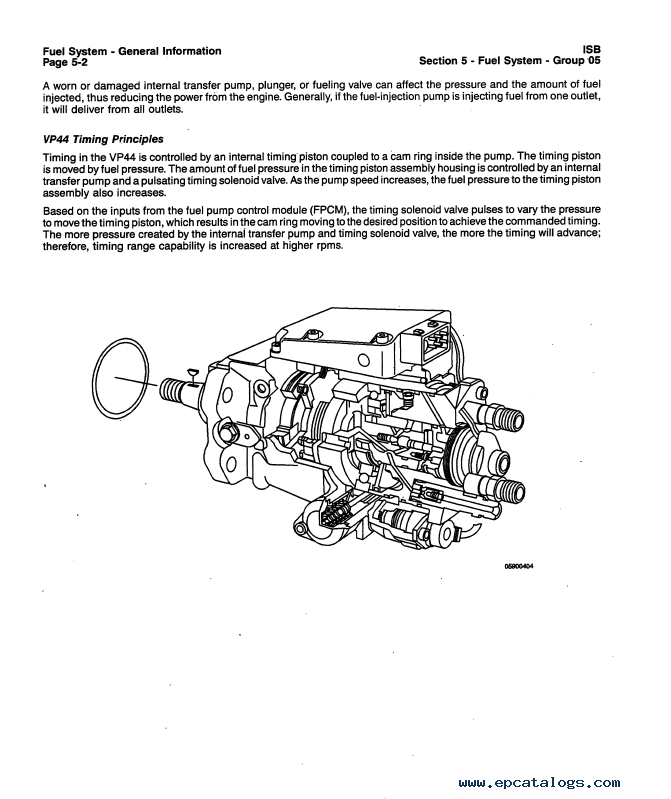
- Fuel Injection Pump, Rotary
- Fuel Lift Pump
- Fuel Pump Support Bracket
- Fuel Pump Timing
- Fuel System - General Information
- Service Tools
- Specifications
- Stall Speed Checklist
- Stall Speed Test
- Section 6 - Injection and Fuel Lines - Group 06
- Air in Fuel
- Fuel Connector (Head Mounted)
- Fuel Drain Line Restriction
- Fuel Drain LInes
- Fuel Filter (Canister Type)
- Fuel Filter (Spin-On Type)
- Fuel Inlet Restriction
- Fuel Return Overflow Valve
- Fuel Supply Lines
- Injector
- Injector Supply Lines (High Pressure)
- Injectors and Fuel Lines - General Information
- Service Tools
- Section 7 - Lubricating Oil System - Group 07
- Engine Oil Heater
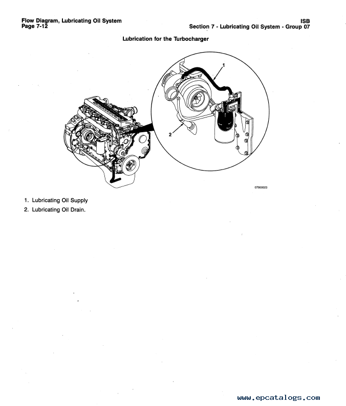
- Flow Diagram, Lubricating Oil System
- Lubricating Oil Cooler
- Lubricating Oil Dipstick
- Lubricating Oil Dipstick Tube
- Lubricating Oil Filter (Spin-On)
- Lubricating Oil Pan
- Lubricating Oil Pressure (Main Rifle)
- Lubricating Oil Pressure Sensor, OEM
- Lubricating Oil Pump
- Lubricating Oil Suction Tube (Block-Mounted)
- Lubricating Oil System - General Information
- Service Tools
- Specifications
- Section 8 - Cooling System - Group 08
- Coolant Heater
- Coolant Temperature Gauge
- Coolant THermostat
- Cooling System
- Cooling System Diagnostics
- Drive Belt, Cooling Fan
- Fan Clutch, On-Off
- Fan, Cooling
- Fan Hub, Belt Driven
- Fan Shroud Assembly
- Fan Spacer and Pulley
- Flow Diagram, Cooling System
- Radiator
- Radiator Hoses
- Radiator Pressure Cap
- Radiator Shutter Assembly
- Service Tools
- Specifications
- Water Pump
- Section 9 - Drive Units - Group 09
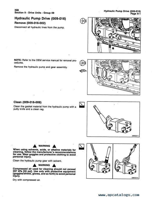
- Hydraulic Pump Drive
- Hydraulic Pump Drive Gear and Shaft
- Section 10 - Air Intake System - Group 10
- Air Crossover
- Air Inlet Connection
- Air Intake Manifold
- Air Intake Restriction
- Air Intake System - General Information
- Air Leaks, Air Intake and Exhaust Systems
- Boost Pressure
- Charge Air Cooler (CAC)
- Cold Starting Aid
- Flow Diagram, Air Intake System
- Service Tools
- Specifications
- Turbocharger
- Turbocharger Axial Clearance
- Turbocharger Blade Damage
- Turbocharger Compressor Seal Leaks
- Turbocharger Oil Drain Line
- Turbocharger Oil Supply Line
- Turbocharger Radial Bearing Clearance
- Turbocharger Turbine Seal Leaks
- Turbocharger Wastegate Actuator
- Turbocharger Wastegate Valve Body
- Section 11 - Exhaust System - Group 11
- Exhaust Manifold, Dry
- Exhaust Restriction
- Flow Diagram, Exhaust System
- Service Tools
- Specifications
- Section 12 - Compressed Air System - Group 12
- Air Compressor
- Air Compressor Carbon Buildup
- Air COmpressor Coolant Lines
- Air Compressor Cylinder Head (Holset QE Models)
- Air Compressor Unloader and Valve Assembly
- Air Governor (Air Compressor Pumps Continuously)
- Air Governor (Air Compressor Will Not Pump)
- Air Leaks, Compressed Air System
- Compressed Air System - General Information
- Flow Diagram, Compressed Air System
- Service Tools
- Section 13 - Electrical Equipment - Group 13
- Alternator
- Alternator Bracket
- Batteries
- Battery Cables and Connections
- Belt Tensioner, Automatic
- Charging System Indicator
- Electrical Equipment - General Information
- Service Tools
- Starter Magnetic Switch
- Starter Solenoid
- Starter Switch
- Starting Motor
- Section 14 - Engine Testing - Group 14
- Engine Run-In (Chassis Dynamometer)
- Engine Run-In (Engine Dynamometer)
- Engine Run-In (Without Dynamometer)
- Engine Testing - General Information
- Engine Testing (Chassis Dynamometer)
- Engine Testing (Engine Dynamometer)
- Engine Testing (In Chassis)
- Service Tools
- Section 16 - Mounting Adaptations - Group 16
- Engine Support Bracket, Front
- Engine Support Bracket, Rear
- Flywheel
- Flywheel Housing
- Flywheel Ring Gear
- Service Tools
- Section 17 - Miscellaneous - Group 17
- Cup Plug
- Pipe Plug
- Service Tools
- Straight Thread Plug
- Section 20 - Vehicle Braking - Group 20
- Section L - Service Literature
- Additional Service Literature
- Service Literature Ordering Location
- Section M - Component Manufacturers
- Component Manufacturers Addresses
- Section V - Specifications
- Air Intake System - Specifications
- Air Intake System - Torque Values
- Cam Followers/Tappets - Specifications
- Capscrew Markings and Torque Values
- Compressed Air System - Specifications
- Compressed Air System - Torque Values
- Cooling System - Specifications
- Cooling System - Torque Values
- Cylinder Block - Specifications
- Cylinder BLock - Torque Values
- Cylinder Head - Specifications
- Cylinder Head - Torque Values
- Drive Belt Tension
- Electrical Equipment - Torque Values
- Engine Testing - Specifications
- Exhaust System - Specifications
- Fraction, Decimal, Millimeter Conversions
- Fuel System - Torque Values
- Injectors and Fuel Lines - Specifications
- Injectors and Fuel Lines - Torque Values
- Lubricating Oil System - Specifications
- Lubricating Oil System - Torque Values
- Mounting Adaptations - Specifications
- Mounting Adaptations - Torque Values
- Newton-Meter to Foot-Pound Conversion Chart
- Pipe Plug Torque Values
- Rocker Levers - Specifications
- Rocker Levers - Torque Values
- Tap-Drill Chart - U.S. Customary and Metric
- Weights and Measures - Conversion Factors
- Section X - Index
Our company provides for sale original spare part catalogs, workshop manuals, diagnostic software for all models of engines, cars, trucks, buses, forklifts, tractors, harvesters, cranes, buldozers, generators, construction and agricultural machines, motorcycles. To purchase a catalog online, please add the product to your cart, fill in the contact form online. Our managers proceed your order the same day.


![spare parts catalog CLAAS Parts Doc Offline Update v919 [02.2026]](/imgs/type_zapch.gif)