
![spare parts catalog CLAAS Parts Doc Offline Update v919 [02.2026]](/imgs/type_zapch.gif)
The Claas parts catalog 02/2026 Upd 915 features step-by-step service procedures, repair illustrations, detailed wiring diagrams, and manufacturer specifications and are easy to follow.
200$
[02/2026]
| |
| Type of catalogue: | repair manual |
| Make: | Hyundai |
| Region: | WorldWide |
| Inclusive languages: |
English |
| Amount of disks: |
1 CD, HTML, PDF |
| Availibility | Instant Download |
| OS: | Windows XP 32 bit, Windows 7 32 bit, Windows 7 64 bit, Windows 8/8.1 32 bit, Windows 8/8.1 64 bit, Windows 10 32 bit, Windows 10 64 bit, Windows 11 64 bit, Windows 11 Pro 64 bit |
| Price, USD: | 49 |
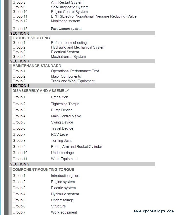
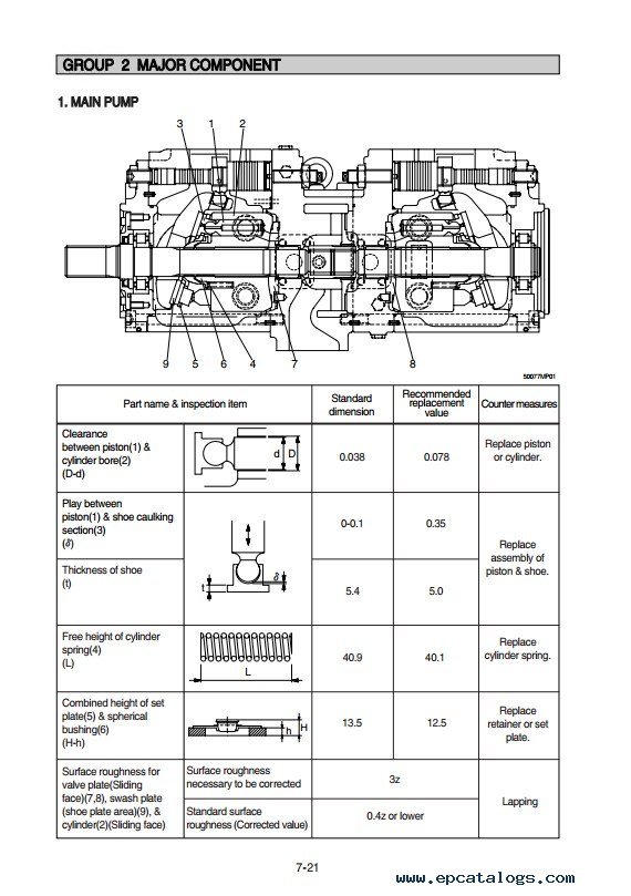
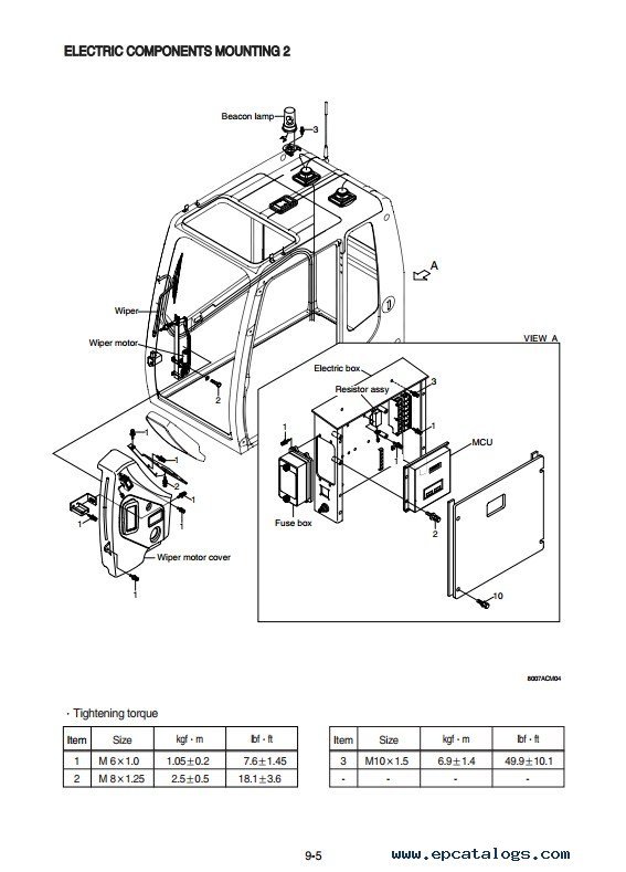
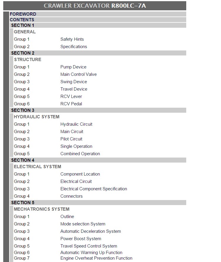
This PDF service manual contains detailed maintenance and troubleshooting information, technical specifications, diagrams, schematics and charts for the Hyundai R800LC-7A crawler excavator model.
This technical repair manual provides step-by-step instructions and detailed descriptions of repair and service procedures, as well as an abundance of pictures and extensive background data to help you choose the right repair procedure for your needs. This service manual is designed to assist service station and repair shop personnel, as well as car owners.
To purchase this manual, click the 'Buy Now' button. Fill out the form and, within a few minutes, you will receive an email containing all the necessary recommendations and installation instructions. If you have any questions or suggestions, please contact us. You can also preview the manual's contents in the list below before buying. Our managers will answer all your questions.
R800LC-7A
Delivered in PDF format, the guide allows you to search for information easily and print complete sections or individual pages as needed. For the best experience, it’s recommended to use Adobe PDF Reader to ensure that all diagrams and graphics are displayed correctly. The set of Manuals is available as an instant digital download in PDF format immediately after purchase. No physical shipping is required - you’ll receive access to the files right away, ready to view or print on any device.
All documents are verified for readability and accuracy. You can save the manual to your computer, tablet, or smartphone and use it offline anytime, ensuring you always have critical repair and maintenance information at hand.
Our company provides for sale original spare part catalogs, workshop manuals, diagnostic software for all models of engines, cars, trucks, buses, forklifts, tractors, harvesters, cranes, buldozers, generators, construction and agricultural machines, motorcycles. To purchase a catalog online, please add the product to your cart, fill in the contact form online. Our managers proceed your order the same day.
VMWare Microcat V6 Hyundai Parts Catalog 09/2025 WorldWide
The VMWare Hyundai Microcat V6 09/2025 OEM Parts Catalog is intended for Hyundai cars and components and contains information for the model range of trucks and buses of this brand.
150$
[09/2025]
|

Hyundai Heavy Equipment Service Manuals 2024 Full Set Offline
Full set of Hyundai heavy equipment manuals for Crawler Excavators, Wheel Loaders, Wheel Excavators, Backhoe Loaders, Skid Steer Loaders and Road Rollers, represented as set of html and pdf documents with easy humam friendly interface. No installation required. Copy and use!
400$
[2024]
|
HYUNDAI USA CANADA Snap-On EPC [01.2021] Spare Parts Catalog![spare parts catalog HYUNDAI USA CANADA Snap-On EPC [01.2021] Spare Parts Catalog](https://www.epcatalogs.com/file/base/7wCEvBLSdZwzQlUnqx3OWQi1gx5ZeQk2kO4JXX2y2BnJtdSoOXutzZyOCc8MY0O8WIQ=/hyundai-usa-canada-snap-on-epc-01.2021-spare-parts-catalog.webp)
Spare Parts Catalog Hyundai is a complete set of original spare parts for the vehicle company Hyundai in the USA and Canada region.
150$
[01/2021]
|
Hyundai Microcat V6 09/2025 OEM Parts Catalog (With Flash Player Hotfix)
Hyundai Microcat V6 09/2025 OEM Parts Catalog is intended for Hyundai vehicles, trucks, and buses. The application covers all regions except the domestic market. The parts manual is a Windows desktop application. You can get it with Digital Download or worldwide shipping on a DVD set.
150$
[09/2025]
|

© 2026 epcatalogs.com Hyundai Crawler Excavator R800LC-7A Service Manual PDF, Heavy Technics + Repair, repair manual |
Terms of Service | DMCA Notice Of Copyright Infringement |


|