
![spare parts catalog CLAAS Parts Doc Offline Update v919 [02.2026]](/imgs/type_zapch.gif)
The Claas parts catalog 02/2026 Upd 919 features step-by-step service procedures, repair illustrations, detailed wiring diagrams, and manufacturer specifications and are easy to follow.
200$
[02/2026]
| |
| Type of catalogue: | repair manual |
| Make: | Cummins |
| Region: | WorldWide |
| Inclusive languages: |
English |
| Amount of disks: |
1 CD, 79,7 МB |
| Availibility | Instant Download |
| OS: | Windows XP 32 bit, Windows 7 32 bit, Windows 7 64 bit, Windows 8/8.1 32 bit, Windows 8/8.1 64 bit, Windows 10 32 bit, Windows 10 64 bit |
| Price, USD: | 49 |
This Troubleshooting and Repair Manual describes all procedures for use, current repair, routine maintenance, troubleshooting which will help you in any problems or situations with Cummins Electronic Control System C8.3 Marine Engines models. Also, you can find information about the specification, illustrations, safety instructions, engine, and system identification, the section about the service tools, schemes, diagrams and other general information about Cummins Electronic Control System C8.3 Marine Engines models.
All screenshots will help you easy to understand the text and locate faults or necessary details. Please, read and understand all of the safety precautions and warnings before performing any use( repair or service). Follow all the recommendations you read in this file and use your device and do not worry about any procedures.
The manual format is a compressed Portable Executable file, only with Windows OS family. This Troubleshooting and Repair Manual will be work in any Windows. Working with this tutorial, you can easily copy, save, and print the information you need. The information was written in English. For any questions, please contact us. We will be happy to help you.
Section i - Introduction
About the Manual
How to Use the Manual
Symbols
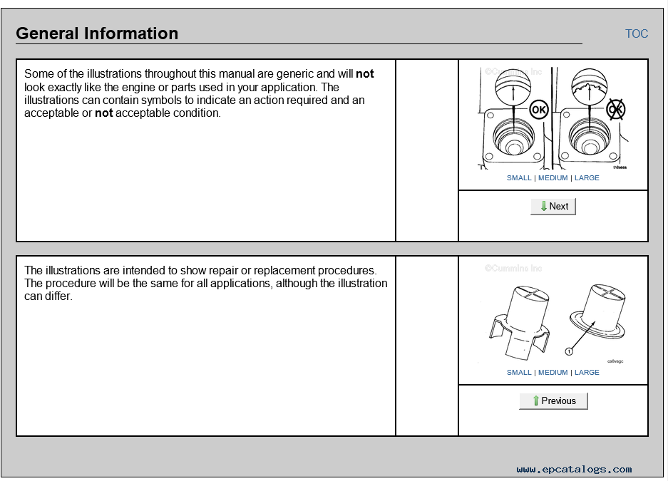
Illustrations
General Safety Instructions
General Repair Instructions
General Cleaning Instructions
Acronyms and Abbreviations
Section E - Engine and System Identification
Engine Identification
Engine Diagrams
Section F - Familiarization
Electronic Controlled Fuel System
Service Tools and Hardware - Overview
Section TF - Troubleshooting Fault Codes
Fault Code Multiple A
Fault Code Multiple B
Electronic Control Module Critical Internal Failure - Bad Intelligent Device or Component
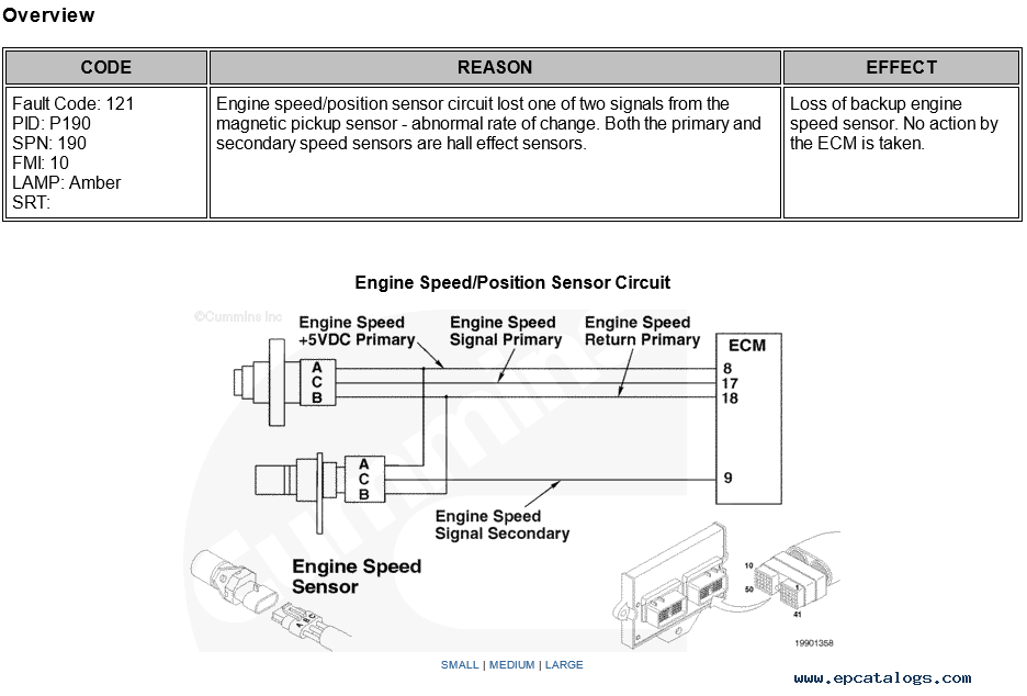
Engine Speed Sensor - Lost Primary Engine Speed Sensor
Engine Speed Sensor - Lost Secondary Engine Speed Sensor
Intake Manifold Pressure Sensor Circuit - Voltage Above Normal or Shorted to High Source
Intake Manifold Pressure Sensor Circuit - Voltage Below Normal or Shorted to Low Source
Intake Manifold Pressure High - Warning
High Voltage Detected at the Throttle Position Signal Circuit
Low Voltage Detected at the Throttle Position Signal Circuit
Backup Throttle Position Sensor - Shorted High
Backup Throttle Position Sensor - Shorted Low
High Pressure Detected at the Oil Pressure Circuit
Low Voltage Detected at the Oil Pressure Circuit
Oil Pressure Signal Indicates Oil Pressure Below the Low Oil Pressure Engine Protection Limit
High Voltage Detected at the Coolant Temperature Circuit
Low Voltage Detected at the Coolant Temperature Circuit
Coolant Temperature Signal Indicates Coolant Temperature Above 104°C [220°F]
High Voltage Detected at the Intake Manifold Temperature Circuit
Low Voltage Detected at the Intake Manifold Temperature Circuit
Intake Manifold Temperature Signal Indicates Temperature Above 88°C [190°F]
The Rack Position Sensor Indicates Rack Position is Greater than the Calibrated ThrePDF ИЛИ shold
Fuel Rack is Stuck in a Position Commanding Excessive Fueling to the Engine
Fuel Rack is Stuck in a Position Providing Adequate or Less than Adequate Fueling to the Engine
Multi-Unit Sync Error
Multi-Unit Sync Switch Error
Section TS - Troubleshooting Symptoms
Troubleshooting Procedures and Techniques
Troubleshooting Symptoms Charts
Engine Acceleration or Response Poor
Engine Difficult to Start or Will Not Start (Exhaust Smoke)
Engine Difficult to Start or Will Not Start (No Exhaust Smoke)
Engine Power Output Low
Engine Runs Rough at Idle
Engine Runs Rough or Misfires
Engine Shuts Off Unexpectedly or Dies During Deceleration
Engine Speed Surges at Low or High Idle
Engine Speed Surges Under Load or in Operating Range
Engine Starts But Will Not Keep Running
Engine Will Not Reach Rated Speed (RPM)
Engine Will Not Shut Off
Fault Code Warning Lamps Stay On (No Apparent Reason)
Fault Code Warning Lamps Do Not Illuminate
Fuel Consumption Excessive
Smoke, Black — Excessive
Section TT- Troubleshooting Symptoms (New Format)
ECM — No Communication Troubleshooting Tree
Section 19 - Electronic Engine Controls - Group 19
Service Tools
Battery Ground Circuit
Engine Coolant Temperature Sensor
Diagnostic Test Mode Switch
Diagnostic Test Mode Switch Circuit
Electronic Control Module (ECM)
ECM Calibration Code
Engine Speed Sensor (ESS)
Engine Wiring Harness
Fault Lamp
Fault Lamp Circuit
Fuel Shutoff Valve Circuit
Fuel Shutoff Valve
Idle Adjust Switch
Idle Adjust Switch Circuit
Intake Manifold Air Temperature Sensor
Intake ManifPDF ИЛИ old Pressure Sensor
Key Switch Battery Supply Circuit
Engine Oil Pressure Sensor
Accelerator Pedal or Lever Position Sensor
Accelerator Pedal or Lever Position Sensor Circuit
Unswitched Battery Supply Circuit
Engine Speed Sensor Circuit
Data Link Circuit, SAE J1939
Data Link Circuit, SAE J1587
Ring Terminal
Fuse, Harness In-Line
Connector, Butt Splice
Weather Pak Connector Series
Metripack Connector Series
AMP Connector Series
Deutsch™ DRC Connector Series
Deutsch™ DT Connector Series
Deutsch™ DTM and DTP Connector Series
Deutsch™ HD10 Connector Series
Deutsch™ HDP20 and HD30 Connector Series
ITT Cannon Connector Series
AMP VP44 Connector Series
Packard Relay Connector
Ford™ Connector Series
D-Sub Miniature Connector Series
Bosch® ECM Injector Driver Connector Series
Bosch® ECM Actuator and Sensor Connector Series
Bosch® ECM OEM Connector Series
Framatome Connector Series
Augat Connector Series
Multimeter Usage
Resistance Measurement Using a Multimeter and a Wiring Diagram
Component Connector and Pin Inspection
(99-019-362) Inactive or Intermittent Fault Code
(105-019-428) Engine Datalinks
Section L - Service Literature
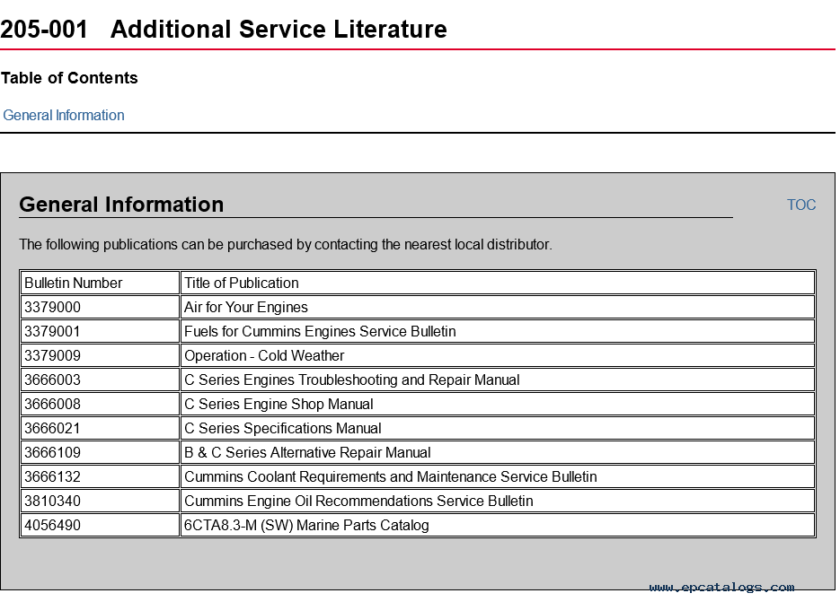
Additional Service Literature
Service Literature Ordering Location
Cummins Customized Parts Catalog
Section V - Specifications
Specifications
Drive Belt Tension
Capscrew Markings and Torque Values
Fraction, Decimal, Millimeter Conversions
Newton-Meter to Foot-Pound Conversions
Pipe Plug Torque Values
Tap-Drill Chart - U.S. Customary and Metric
Weights and Measures - Conversion Factors
Our company provides for sale original spare part catalogs, workshop manuals, diagnostic software for all models of engines, cars, trucks, buses, forklifts, tractors, harvesters, cranes, buldozers, generators, construction and agricultural machines, motorcycles. To purchase a catalog online, please add the product to your cart, fill in the contact form online. Our managers proceed your order the same day.


© 2026 epcatalogs.com Cummins Electronic Control System C8.3 Marine Engines Troubleshooting and Repair Manual, Heavy Technics + Repair, repair manual |
Terms of Service | DMCA Notice Of Copyright Infringement |


|