
Challenger Rubber Track Tractor MT845E, MT855E, MT865E, MT875E Workshop Service Manual PDF
[11/2015]
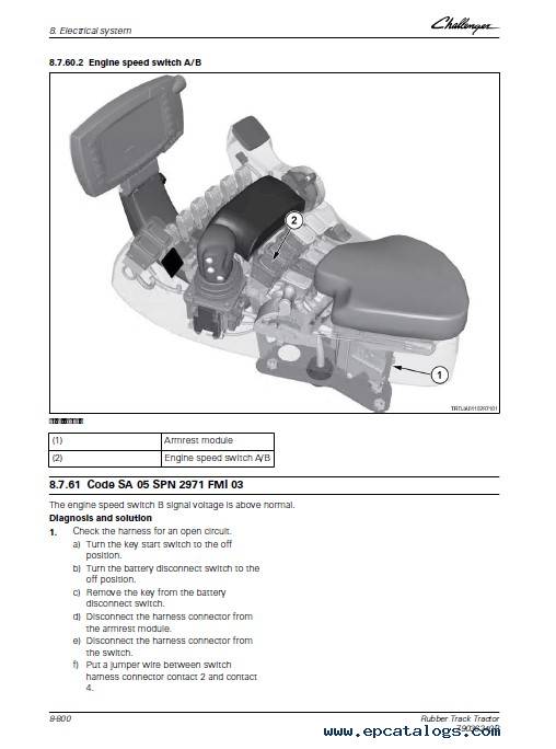
For complete service information also see:
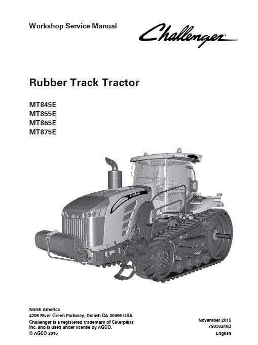
Challenger Rubber Track Tractor MT845E, MT855E, MT865E, MT875E Operator’s Manual
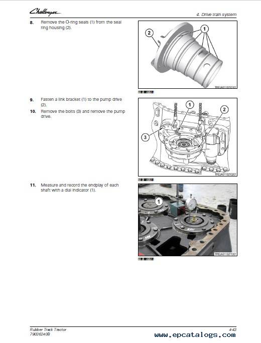
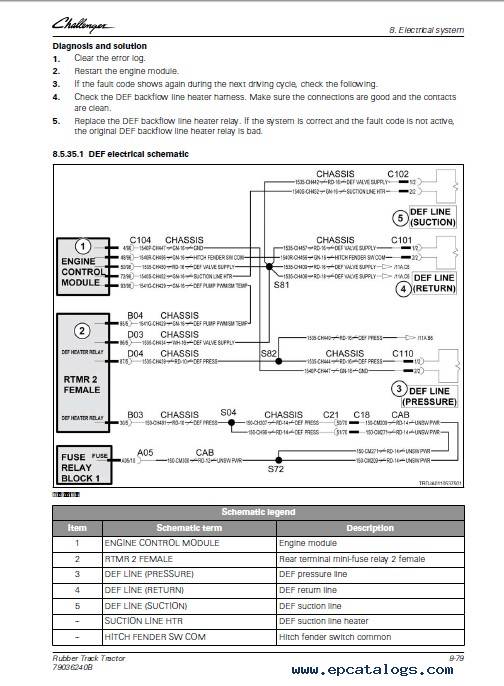
This PDF Workshop Service Manual is intended to assist with workshop operations and repair work of Challenger Rubber Track Tractor MT845E, MT855E, MT865E, MT875E Models. This guide contains many illustrations and diagrams with which to rectify the fault and failure.
This is an electronic database containing service and repair manuals, complete technical material about technical maintenance, repair instructions, information about spare parts and accessories for Challenger tractors. In addition, this tutorial includes many helpful pictures, different diagrams, and photos with step-by-step instructions and descriptions that will help to identify the breakdown, damage, or other problems.
This workshop service manual is a PDF file. Installation of this manual is very easy (Instant Download). To work with the repair manual, you have to use any PDF Reader (for example, Adobe Reader).
It is easy to purchase this product. Just click on the 'Buy Now' button and follow the instructions. After payment, you will get the link for downloading your PDF Workshop Service Manual. So, after a few minutes, you will get your guide and you can start studying it.
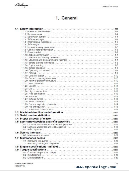
Models covered:
MT845E,
MT855E,
MT865E,
MT875E.
Contents:
- 1 General
- 1.1 Safety information
- 1.2 Machine identification information
- 1.3 Serial number definition
- 1.4 Proper disposal of waste
- 1.5 Lubricant viscosities and refill capacities
- 1.6 Service intervals
- 1.7 Maintenance access
- 1.8 Engine specification - MT800E
- 1.9 Torque specifications
- 1.10 Dimensions
- 1.11 Shipping weights
- 1.12 Machine specifications - MT800E
- 2 Engine, fuel, and exhaust system
- 2.1 Engine maintenance
- 2.2 Engine system components
- 2.3 Flushing and refilling the cooling system
- 2.4 Engine troubleshooting
- 2.5 Fuel system components
- 2.6 Exhaust system components
- 2.7 SCR system
- 2.8 Fluid specifications
- 2.9 Safety instructions
- 2.10 To the user
- 2.11 Engine construction
- 2.12 Technical data
- 2.13 Liquid quality requirements
- 2.14 Tightening torques
- 2.15 Special tools
- 2.16 Flywheel housing
- 2.17 Flywheel
- 2.18 Fitting the crankshaft hub
- 2.19 Timing gear assembly
- 2.20 Lubrication system
- 2.21 Cooling system
- 2.22 Air control system maintenance
- 2.23 Fuel system
- 2.24 SCR system
- 2.25 Engine control system
- 2.26 Terminal diagram
- 3 Steering system
- 3.1 Steering system introduction
- 3.2 Main steering system components
- 3.3 Steering electrical system
- 3.4 Steering hydraulic system
- 3.5 Position of electronic components
- 3.6 Position of hydraulic components
- 3.7 Steering system components
- 3.8 Steering system test and adjust
- 3.9 Steering system maintenance
- 4 Drive train system
- 4.1 Transmission system
- 4.2 Transmission
- 4.3 Drive train components
- 4.4 FInal drive
- 4.5 Steering differential
- 4.6 Steering motor drive
- 4.7 Drive train maintenance
- 4.8 Drive train system testing and adjusting
- 5 Brake system
- 5.1 Service brake system
- 5.2 Hydraulic trailer brake system
- 5.3 Air trailer brake system
- 5.4 Park brake system
- 5.5 Brake system disassembly and assembly
- 5.6 Brake system test and adjust
- 5.7 Brake system troubleshooting
- 6 Compressed air system
- 6.1 Air system operation
- 6.2 Air system components
- 6.3 Air compressor
- 6.4 Air dryer
- 6.5 Main air reservoir
- 6.6 Air regeneration reservoir
- 6.7 Air trailer brakes
- 6.8 Air system components specifications
- 7 Hydraulic system
- 7.1 Hydraulic system operation
- 7.2 Hydraulic system components
- 7.3 Hydraulic system testing and adjusting
- 7.4 Hydraulic system maintenance
- 7.5 Implement system troubleshooting
- 8 Electrical system
- 8.1 General information
- 8.2 Main fuse panel
- 8.3 Electrical system components
- 8.4 Electrical system troubleshooting
- 8.5 00 ENgine module
- 8.6 03 Transmission
- 8.7 05 Armrest module
- 8.8 161 Auxiliary valves 1 module
- 8.9 162 Auxiliary valves 2 module
- 8.10 163 Auxiliary valves 3 module
- 8.11 164 Auxiliary valves 4 module
- 8.12 165 Auxiliary valves 5 module
- 8.13 166 Auxiliary valves 6 module
- 8.14 171 3-Point linkage valve module
- 8.15 175 Unassigned auxiliary valve module
- 8.16 208 Front-lighting module
- 8.17 209 Roof lighting module
- 8.18 210 Rear lighting module
- 9 Cab
- 9.1 Removing and installing the cab
- 9.2 Primary fresh air filter
- 9.3 Recirculation filter
- 9.4 Filter maintenance
- 9.5 Armrest
- 9.6 Cab seat
- 9.7 Cab switches
- 9.8 Steering console
- 10 Air conditioning and heating system
- 10.1 Air conditioning and heating system
- 10.2 Testing and adjusting
- 10.3 Basic air conditioning system testing
- 10.4 Manifold gauge set readings
- 10.5 Checking the system pressure
- 10.6 Refrigerant recovery
- 10.7 Air conditioning and heating system components
- 10.8 Heating and air conditioning troubleshooting
- 11 Chassis
- 11.1 Engine cover
- 11.2 Hadrall
- 11.3 Steps
- 11.4 Platforms
- 12 Track belt system
- 12.1 Undercarriage (Mobil Trac) system operation
- 12.2 Undercarriage (Mobil Trac) system components
- 12.3 Undercarriage (Mobil Trac) width adjustment
- 12.4 Track detension/tension
- 12.5 Mobil-Trac track system
- 12.6 Replacing the track
- 12.7 Track alignment
- 12.8 Undercarriage (Mobil-Trac) components removal and installation
- 12.9 Undercarriage (Mobil-Trac) maintenance
- 13 Implement drive system
- 13.1 Power take-off system
- 13.2 Power take-off
- 13.3 Power take-off system testing and adjusting
- 14 Implement lift system
- 14.1 3-point linkage system introduction
- 14.2 3-point linkage components
- 14.3 Position of electronic components
- 14.4 POsition of hydraulic components
- 14.5 3-point linkage system options
- 14.6 3-point linkage system control settings
- 14.7 3-point linkage control valve
- 14.8 Steerable 3-point linkage control valve operation
- 14.9 3-point linkage disassembly and assembly
- 14.10 3-point linkage system testing and adjusting
- 14.11 3-point linkage troubleshooting
- 15 Attachments
- 15.1 Drawbar maintenance
- 15.2 Ballast
- 15.3 Weight removal and installation
- 16 Diagrams
- 16.1 Hydraulic schematics
- 16.2 Electrical schematics
- 17 Special tools
- 17.1 Drive train special tools
- 18 Index
Screenshots for Challenger Rubber Track Tractor MT845E, MT855E, MT865E, MT875E Workshop Service Manual PDF:
Our company provides for sale original spare part catalogs, workshop manuals, diagnostic software for all models of engines, cars, trucks, buses, forklifts, tractors, harvesters, cranes, buldozers, generators, construction and agricultural machines, motorcycles. To purchase a catalog online, please add the product to your cart, fill in the contact form online. Our managers proceed your order the same day.
Related products for Challenger Rubber Track Tractor MT845E, MT855E, MT865E, MT875E Workshop Service Manual PDF:
![]() ![]() Challenger AG Europe Parts Catalog & Workshop Service Manuals 09/2020![]() Parts Catalog for Europe contains all the technical information about agricultural equipment and spare parts of the company Challenger, Concern AGCO.16BJ
150$
[09/2020]
|
![]() ![]() Challenger AG USA Parts Catalog & Workshop Service Manuals 2020![]() Challenger Parts USA is an electronic catalog of spare parts for all agricultural and other types of equipment Challenger, for materials processing.
150$
[09/2020]
|
![]() Challenger Repair Europe![]() Challenger Repair Europe is an electronic database catalog of spare parts of agricultural machinery Challenger, which combines outstanding performance and high reliability Challenger. The catalog of spare parts Challenger Repair Europe contains a list of such items as brakes, radiators, front and rear suspension parts, generators and other equipment parts for Challenger.
150$
[02/2012]
|
![]() Challenger Repair USA![]() Repair instructions for Challenger equipment
150$
[02/2012]
|