This manual addresses the professionally qualified personnel or the after-sales service of the BOMAG single drum roller BW series and should be of help and assistance in the correct and efficient repair and maintenance work.
The electronic manual contains full technical information, instructions on proper organization of repair and maintenance, and instructions for use and installation. This manual helps troubleshoot problem areas, troubleshoot computer systems, and eliminate of hardware conflicts. This manual describes the disassembly, dismantling, assembly, installation, and repair of components and assemblies.
All information is divided into thematic sections, a list of which you can see below in the content. This will help you quickly navigate a difficult situation and easily find the information you need. Factory guides include many different diagrams and schemes, which you can visually inspect and familiarize yourself with in detail, as well as provide first aid.
The service manual comes in PDF format in English. You can buy this product in one click. After you receive the manual, we will send all the instructions needed to install and use it, and provide after-sales support. For work with this tutorial, we recommend using the Adobe PDF Reader application.
Models & S/N:
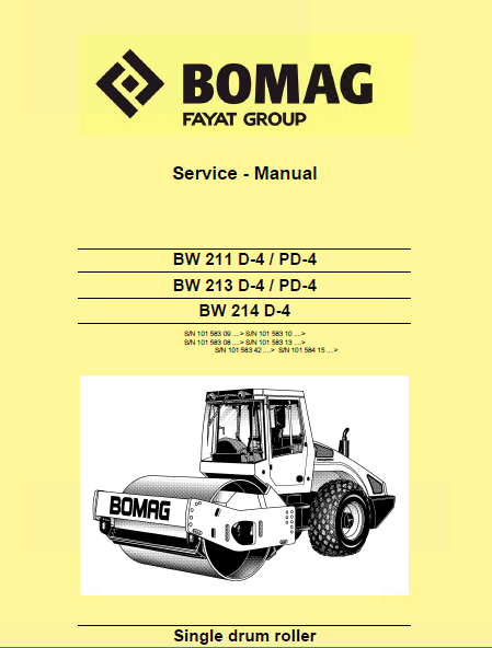
BW 211 D-4 / PD-4
BW 213 D-4 / PD-4
BW 214 D-4
S/N 101 583 09 > S/N 101 583 10 >
S/N 101 583 08 > S/N 101 583 13 >
S/N 101 583 42 > S/N 101 584 15 >
CONTENTS:
- General
- 1.1 Introduction
- 1.2 Safety regulations
- 1.3 General repair instructions
- 1.4 Tightening torques
- Technical data
- Maintenance
- 3.1 General notes on maintenance
- 3.2 Fuels and lubricants
- 3.3 Table of fuels and lubricants
- 3.4 Running-in instructions
- Caddy wiring diagrams
- 4.1 Understanding circuit diagrams
- 4.2 Circuit symbols in the circuit diagram
- 4.3 Identification of switch blocks in the Caddy wiring diagram
- 4.4 Designation of components in the wiring diagram
- 4.5 Terminal designations in wiring diagram
- E-Plan wiring diagrams
- 5.1 Understanding wiring diagrams
- 5.2 Circuit symbols in the circuit diagram
- 5.3 Identification of switch blocks in the wiring diagram
- 5.4 Designation of components in the wiring diagram
- 5.5 Terminal designations in wiring diagram
- Electrics
- 6.1 Battery ground and analog ground
- 6.2 Current and voltage
- 6.3 Pulse Width Modulation (PWM)
- 6.4 Resistance
- 6.5 Series / parallel connection
- 6.6 Ohm's law
- 6.7 Electrical energy
- 6.8 Formula diagram
- 6.9 Metrology
- 6.10 Diodes, relays, fuses
- 6.11 Telemecanique switch
- 6.12 Plug connectors
- 6.13 Magnetic coil plug
- 6.14 Deutsch plug, series DT and DTM
- 6.15 Plugs and terminals in spring clamping technology
- 6.16 Acceleration transducer
- 6.17 Proximity switches
- 6.18 Level sensor in diesel tank (R03)
- 6.19 Differential pressure switch for hydraulic oil filter, B21
- 6.20 Oil pressure switch, B06
- 6.21 Air filter vacuum switch, B03
- 6.22 Sensor, water in fuel filter, B124
- 6.23 Charge control light (H08), operating hour meter (P00)
- 6.24 Float switch, coolant tank, B55
- 6.25 Coolant temperature switch, B30
- 6.26 Disassembling and assembling the coolant temperature switch
- 6.27 Boost fuel solenoid valve
- 6.28 Engine solenoid to shit down the engine, Y13
- 6.29 Electric throttle control
- 6.30 Fuel preheating, R79
- 6.31 Heating flange on engine, R19
- 6.32 Checking the heating flange control
- 6.33 Engine monitoring
- 6.34 Batteries
- 6.35 Battery service
- 6.36 Main battery fuse
- 6.37 Starting with jump wires
- 6.38 Generator
- 6.39 Replacing the voltage regulator
- 6.40 Electric starter
- 6.41 Disassembling and assembling the starter
- 6.42 Overview of electric components
- 6.43 Operator's stand, old design
- 6.44 Operator's stand, new design
- 6.45 Cabin
- 6.46 Fuses, old design
- 6.47 Fuses, new design
- 6.48 Electronic control units
- 6.49 Checking the voltage supply for the control unit
- 6.50 Diagnostics concept
- Electronic modules
- 7.1 BEM, BOMAG Evib-meter
- 7.2 Electrics module A68
- 7.3 Electric module K04
- 7.4 Electric module A72, old design
- 7.5 Electric module A108
- Speedometer Module
- 582 502 15 dust protection / 582 502 16 gasket
- 9.1 Assembling the dust protection
- Hydraulics
- 10.1 Hydraulic circuit
- 10.2 Connection overview
- 10.3 Travel pump 075
- 10.4 Vibration pump 42R 041
- 10.5 Axial piston swash plate principle / pump
- 10.6 Troubleshooting axial piston pumps
- 10.7 Travel motor 51 C/D 110
- 10.8 Trouble shooting, variable displacement axial piston motor
- 10.9 Drum drive motor MSE 02
- 10.10 Vibration motor A10FM 45
- 10.11 Axial piston swash plate principle / motor
- 10.12 External gear pumps
- 10.13 Travel circuit
- 10.14 Stopping the machine, operating the parking brake
- 10.15 Towing in case of an engine failure
- 10.16 Adjust the parking brake
- 10.17 Vibration circuit
- 10.18 Steering circuit
- 10.19 Check the hydraulic oil level
- 10.20 Changing hydraulic oil and breather filter
- 10.21 Changing the hydraulic oil filter
- 10.22 Changing the bypass filter
- Tests and adjustments
- 11.1 Special tools, tests and adjustments
- 11.2 Checking the rotation speeds
- 11.3 Checking / adjusting the neutral positions of the travel pump
- 11.4 Pressure tests in the travel circuit
- 11.5 Checking / adjusting the vibrator shaft speeds
- 11.6 Pressure measurements in the vibration circuit
- 11.7 Check the leakage rate of the vibration motor
- 11.8 Pressure test in steering circuit
- Flushing and bleeding
- 12.1 Special tools for flushing
- 12.2 Flushing - general
- 12.3 Flushing schematic travel circuit (distribution travel pump)
- 12.4 Flushing the travel circuit (travel pump distribution)
- 12.5 Flushing schematic travel circuit (distribution axle motor)
- 12.6 Flushing the travel circuit (axle motor distribution)
- 12.7 Flushing schematic for vibration drive
- 12.8 Flushing the vibration circuit
- 12.9 Bleeding the travel circuit
- 12.10 Bleeding the vibration circuit
- Engine
- 13.1 Diesel engine
- 13.2 Fuel filter and check valve
- 13.3 Check, clean the water separator
- 13.4 Change the fuel pre-filter cartridge
- 13.5 Change the fuel filter cartridge
- 13.6 Changing engine oil and oil filter cartridges
- 13.7 Removing and installing the thermostat
- 13.8 Checking the thermostat in disassembled state
- 13.9 Change the coolant
- 13.10 Checking the anti-freeze concentration
- 13.11 Checking / replacing the ribbed V-belt
- 13.12 Combustion air filter service
- 13.13 Crankcase - disassembling and assembling the ventilation valve
- 13.14 Adjusting the valve clearance
- 13.15 Adjusting the control piston play
- 13.16 Checking the compression
- 13.17 Engine
- 13.18 Special tools, Deutz engine (TCD 2013 2V)
- Air conditioning system
- 14.1 Physical basics
- 14.2 Refrigerant R134a
- 14.3 Compressor oil / refrigeration oil
- 14.4 Working principle of the air conditioning system
- 14.5 Monitoring devices
- 14.6 Description of components
- 14.7 Measuring the compressor oil level
- 14.8 Checking the magnetic clutch
- 14.9 Inspection and maintenance work
- 14.10 Checking, replacing the refrigerant compressor V-belt
- 14.11 Air conditioning service (old design)
- 14.12 Service the air conditioning
- 14.13 Drying and evacuation
- 14.14 Emptying in case of repair
- 14.15 Leak test
- 14.16 Filling instructions
- 14.17 Trouble shooting in refrigerant circuit, basic principles
- 14.18 Trouble shooting, refrigerant circuit diagram
- 14.19 Trouble shooting procedure
- 14.20 Steam table for R134a
- Cabin assembly
- 15.1 Preparations
- 15.2 Cabin assembly
- 15.3 Final function tests and checks
- Replacing the cab window panes
- 16.1 Assembly of window panes
- 16.2 Special tools, cabin windows
- 16.3 Auxiliary materials
- 16.4 Removing and installing the window pane
- Drum
- 17.1 Special tools, drum, single drum rollers
- 17.2 Repair overview for drum
- 17.3 Removing and installing the drum
- 17.4 Repairing the drum
- 17.5 Dismantling, assembling the change-over weights
- 17.6 Changing the rubber buffers and adjusting the pretension
- Oscillating articulated joint
- 18.1 Special tools, oscillating articulated joint (BW177 to BW 216)
- 18.2 Repair overview oscillating articulated joint
- 18.3 Removing and installing the oscillating articulated joint
- 18.4 Dismantling the oscillating articulated joint
- 18.5 Assembling the oscillating articulated joint
- Suppliers documentation
- 19.1 Travel pump
- 19.2 Vibration pump
- 19.3 Drum drive
- 19.4 Vibration motor
- 19.5 Axle drive motor
- 19.6 Steering valve
- 19.7 Axle
- Circuit diagrams
- 20.1 Hydraulic diagram 581 202 03
- 20.2 Wiring diagram 582 702 09
- 20.3 Wiring diagram 582 702 29
- 20.4 Wiring diagram 582 702 41
- 20.5 Wiring diagram 9
- 20.6 Wiring diagram 62
Manual features:
Format: PDF
Language: English
Compatible with all versions of Windows, Mac, Linux, iPhone, iPad, and Android.
This manual provides step-by-step guides and high-quality illustrations to help you perform routine and preventive maintenance effectively.
FAQs:
How do I download the manual?
After completing your purchase, you will receive a download link via email. Please check your spam/junk folder if you cannot find it in your inbox.
Is the manual printable?
Yes, you can print all pages.
Still have questions?
Leave us a message and we will try to help.
Our company provides for sale original spare part catalogs, workshop manuals, diagnostic software for all models of engines, cars, trucks, buses, forklifts, tractors, harvesters, cranes, buldozers, generators, construction and agricultural machines, motorcycles. To purchase a catalog online, please add the product to your cart, fill in the contact form online. Our managers proceed your order the same day.


![spare parts catalog CLAAS Parts Doc Offline Update v919 [02.2026]](/imgs/type_zapch.gif)