For complete service information also see:
John Deere 6076 OEM Engines And Accessories Parts Catalog PC2182
John Deere 6076 OEM Natural Gas, Diesel Engines, Accessories (Waterloo) Parts Catalog PDF
Periodically, the engines are different kinds of breakdowns and malfunctions. For their elimination and prevent the emergence of new, you should purchase This PDF Component Technical Manual.
Workshop service manual includes full-service information, operation, and maintenance manual, special instructions for repair and maintenance, technical specifications, wiring electrical diagrams, service documentation, and other additional information which is presented specifically for diesel engines company John Deere.
This Component Technical Manual (CTM6) covers the recommended repair procedure for all 6076, 7.6 L (466 cu. In.) Diesel engines, serial no. (-499999), And produced in Waterloo, Iowa.
Manual Contents:
- Group 00—Introduction and Safety Information
- Group 01—General Information
- Inch Series Torque Chart
- Metric Series Torque Chart
- Bolt Identification Chart
- Engine Model Designation
- Engine Nameplate Information
- Option Code Label
- Engine Application Chart
- Basic 6076 Engine Specifications
- General Engine Description
- Engine-Sectional View
- Group 02—Fuels, Lubricants, and Coolant
- Diesel Fuel
- Diesel Engine Oil
- General Purpose Grease
- Engine Coolant Recommendations
- Engine Coolant Requirements
- Group 03—Engine Mounting
- Engine Repair Stand
- Safety Precautions
- Install 400 Series Adapters on Repair Stand
- Engine Lifting Procedure
- Clean Engine
- Disconnect Turbocharger Oil Inlet Line
- Mount Engine On Repair Stand
- Group 04—Engine Rebuild Guide
- 6076 Engine Disassembly Sequence
- Sealant Application Guidelines
- 6076 Engine Assembly Sequence
- Group 05—Cylinder Head and Valves
- Essential Tools
- Service Equipment and Tools
- Other Materials
- Cyl. Head and Valve Specifications
- Diagnosing Malfunctions
- Check and Adjust Valve Clearance
- Check Valve Lift
- Disconnect Turbocharger Oil Inlet Line
- Remove Cylinder Head
- Disassemble and Inspect Rocker Arm
- Shaft Assembly
- Measure Valve Recess
- Remove Valve Assembly
- Inspect and Measure valve Springs
- Inspect Valve Rotators and Wear Caps
- Clean Valves
- Inspect and Measure Valves
- Grind Valves
- Inspect and Clean Cylinder Head
- Check Cylinder Head Flatness
- Measure Cylinder Head Thickness
- Clean Valve Guides
- Measure Valve Guides
- Knurl Guides
- Clean Valve Seats
- Measure Valve Seats
- Grind Valve Seats
- Replace Valve Inserts
- Install Valves
- Inspect and Clean Cylinder Head Nozzle Bore
- Clean and Inspect Push Rods
- Clean and Inspect Cylinder Head Cap Screws
- Inspect and Clean Ventilator Outlet Hose
- Clean and Inspect Top Deck of Cylinder Block
- Measure Cylinder Liner Standout
- Protect Cylinder Block Top Deck
- Assemble Valve Assembly
- Install Cylinder Head
- Tighten Cylinder Head Cap Screws (Grade 180 or 12.9)
- Tighten Flanged-Head Cylinder Head Cap Screws
- TORQUE-TURN Flanged-Head Cap Screws
- Install Rocker Arm Assembly
- Complete Final Assembly Of Injection Pump Side
- Complete Final Assembly On Exhaust Manifold Side
- Perform Engine Break-In
- Group 10—Cylinder Block, Liners, Pistons and Rods
- Essential Tools
- Service Equipment and Tools
- Specifications
- Other Materials
- Diagnosing Malfunctions
- Disconnect Turbocharger Oil Inlet Line
- Remove Pistons and Connecting Rods
- Measure Cylinder Liner Standout
- Remove Cylinder Liners
- Inspect Pistons and Liners
- Measure Oil Control Ring Groove
- Measure Cylinder Liners
- Deglazing Cylinder Liners
- Inspect and Measure Connecting Rod Bearings
- Inspect Rod and Cap
- Inspect Piston Pins and Bushings
- Remove Piston Pin Bushing
- Clean and Inspect Rod Pin Bushing Bore
- Install Rod Pin Bushing
- Complete Disassembly of Cylinder Block (If Required)
- Remove and Clean Piston Cooling Orifices
- Inspect and Clean Cylinder Block
- Clean O-Ring Bore
- Measure Cylinder Block
- Install Piston Cooling Orifices and Gallery Plugs
- Recheck Cylinder Liner Standout
- Measure Liner Flange Thickness
- Install Liner Shims—If Required
- Install Cylinder Liner O-Rings and Packings
- Install Cylinder Liners
- Install Pistons and Connecting Rods
- Use TORQUE-TURN Method For Proper Torque
- Check Engine Rotation for Excessive Tightness
- Complete Final Assembly
- Group 15—Crankshaft, Main Bearings and Flywheel
- Essential Tools
- Service Equipment and Tools
- Other Materials
- Specifications
- Diagnosing Malfunctions
- General Information
- Disconnect Turbocharger Oil Inlet Line
- Remove Crankshaft Real Oil Seal and Wear Sleeve
- /(Without Removing Oil Seal Housing) Install Crankshaft Rear Oil Seal and Wear Sleeve
- /(Without Engine Disassembly) Inspect Vibration Damper
- Remove Water Pump and Damper Pulley
- Remove Timing Gear Cover—Non-Auxiliary Engines
- Remove Auxiliary Drive Gear and Timing Gear Cover
- /—Auxiliary Drive Engines Remove Front Oil Seal From Timing Gear Cover
- Install Front Oil Seal In Timing Gear Cover
- Check Crankshaft End Play
- Remove Front Wear Sleeve
- Remove and Inspect Crankshaft Gear
- Inspect, Measure and Repair Flywheel
- Check Flywheel Housing Face Run-Out
- Check Flywheel Face Flatness
- Check Pilot Bearing Bore Concentricity
- Remove Flywheel
- Remove SAE 1 And SAE 2 Flywheel Housing
- Remove SAE 3 Flywheel Housing
- Replace Flywheel Ring Gear
- Service Clutch Shaft Pilot Bushing-Quad Range Transmissions
- Remove Rear Oil Seal Housing And Wear Sleeve
- /(With Engine Disassembled) Remove Crankshaft Main Bearings
- Check Main Bearing Clearance
- Remove Crankshaft
- Inspect Crankshaft
- Measure Assembled ID of Bearings And OD Of Crankshaft Journals
- Main Bearing Cap Line Bore Specifications
- Thrust Bearing New Part Specifications
- Crankshaft Grinding Guidelines
- Crankshaft Grinding Specifications
- Replace Crankshaft Oil Pump Drive Gear
- Inspect Thrust Bearings
- Remove and Clean Piston Cooling Orifices
- Install Main Bearings and Crankshaft
- Install Oil Pump And Check Drive Gear-To-Crankshaft Clearance
- Install Rear Crankshaft Oil Seal Housing
- Check Oil Seal Housing Runout
- Crankshaft Rear Oil Seal And Wear Sleeve Handling Precautions
- Install Crankshaft Rear Oil Seal And Wear Sleeve (With Engine Disassem
- Install Crankshaft Gear
- Install Front Wear Sleeve
- Install SAE 3 Flywheel Housing
- Install Flywheel
- Install SAE 1 And SAE 2 Flywheel Housing
- Install Timing Gear Cover—Non-Auxiliary Drive Engines
- Install Timing Gear Cover And Auxiliary Drive Idler Gear—Auxiliary Dri
- Install Rear Auxiliary Drive Gear
- Install Damper Pulley Assembly
- Complete Final Assembly
- Group 16—Camshaft and Timing Gear Train
- Essential Tools
- Service Equipment and Tools
- Other Material
- Specifications
- General Information
- Check Valve Lift
- Disconnect Turbocharger Oil Inlet Line
- Prepare Engine For Camshaft Removal
- Remove Damper Pulley and Timing Gear Cover—Non-Auxiliary Drive Engines
- Remove Damper Pulley, Auxiliary Drive Gear and Timing Gear Cover
- /—Auxiliary Drive Engines Remove Front Oil Seal From Timing Gear Cover
- Install Front Oil Seal In Timing Gear Cover
- Check Camshaft End Play
- Measure Camshaft Drive Gear-To-Crankshaft Gear Minimum Backlash
- Remove Camshaft
- Remove Camshaft Gear, Spacer, and Thrust Plate
- Measure Thrust Plate and Spacer
- Inspect And Measure Camshaft Followers
- Visually Inspect Camshaft
- Measure Camshaft Journal OD and Bushing ID
- Measure Camshaft Lobe Lift
- Assemble Camshaft
- Service Camshaft Bushings Using JDG602 Adapter Set
- Service Camshaft Bushings Using JDG606 Adapter Set
- Install Camshaft
- Replace Auxiliary Drive Gear Bearings
- Replace Auxiliary Drive Idler Gear Bearings
- Install Timing Gear Cover—Non Auxiliary Drive Engines
- Install Timing Gear Cover and Auxiliary Drive Gear
- /—Auxiliary Drive Engines Install Rear Auxiliary Drive Gear
- Complete Final Assembly
- Group 20—Lubrication System
- Specifications
- Engine Crankcase Oil Fill Quantities
- Other Material
- How The Lubrication System Works
- Diagnosing Malfunctions
- Disconnect Turbocharger Oil Inlet Line
- Drain Engine Oil and Remove Oil Pan
- Horizontal Oil Filter and Housing Assembly
- Remove Horizontal Oil Filter and Housing Assembly
- Vertical Oil Filter and Housing Assembly
- Remove Vertical Oil Filter and Housing Assemblies
- Inspect Oil Pressure Regulating Valve
- Inspect Oil Filter Bypass Valve
- Install Horizontal Oil Filter and Housing
- Install Vertical Oil Filter and Housing Assemblies
- Remove Engine Oil Cooler
- Clean Inspect, and Install Engine Oil Cooler
- Remove Oil Cooler Bypass Housing
- Remove and Inspect Oil Cooler Bypass Valve
- Engine Oil Pump Assembly—Deep Sump
- Engine Oil Pump Assembly—Standard Sump
- Check Crankshaft Gear-To-Oil Pump Drive Gear Backlash
- Remove Engine Oil Pump
- Inspect and Clean Oil Pump
- Check Drive Shaft End Play
- Check Drive Shaft Side Movement
- Check Pumping Gear Backlash
- Remove And Inspect Oil Pump Drive Gear
- Install Oil Cooler Bypass Valve And Housing
- Adjust Set Screw
- Install Engine Oil Pump
- Install Oil Pan
- Group 25—Cooling System
- Essential Tools
- Other Materials
- Specifications
- How The Cooling System Works
- Diagnosing Malfunctions
- Medium Duty, Adjustable Fan Drive Assembly
- Remove and Install
- Replace Bearings
- Heavy Duty, Adjustable Fan Drive Assembly
- Remove and Install
- Replace Bearings
- Replace Bearings In Water Manifold Mounted, Fixed Fan Drive Assembly
- Remove Water Pump
- Disassemble Water Pump
- Inspect Water Pump Parts
- Assemble Water Pump
- Install Water Pump
- Remove and Test Thermostats
- Install Thermostats
- Remove Water Manifold
- Inspect and Clean Water Manifold
- Install Water Manifold
- Remove Coolant Heater—If Equipped
- Install Coolant Heater—If Equipped
- Complete Final Assembly
- Inspect and Tension Fan and Alternator V-Belts
- Group 30—Air Intake And Exhaust System Essential Tools
- Essential Tools
- Other Material
- Specifications
- How The Air Intake and Exhaust System Works
- How The Turbocharger Works
- How The Turbocharger is Lubricated
- Extending Turbocharger Life
- Diagnosing Turbocharger Malfunctions
- Remove Turbocharger
- Turbocharger Seven-Step Inspection
- Perform Axial End Play Bearing Test (Schwitzer 3LM)
- Perform Radial Bearing Clearance Test (Schwitzer)
- Perform Raidal Bearing Test—(AiResearch/Garrett T04E)
- Disassemble Turbocharger
- Clean and Inspect Turbine and Compressor Housings
- Replace Center Housing and Rotating Assembly
- Prelube Turbocharger
- Install Turbocharger
- Remove and Inspect Intake Manifold (6076T and 6076H Engines)
- Install Intake Manifold (6076T and 6076H Engines)
- How The Aftercooler Works—6076A Engines
- Single-Pass Aftercooler Assembly
- Two-Pass Aftercooler Assembly Remove Aftercooler and Intake Manifold (6076A Engines)
- Inspect and Repair Aftercooler (6076A Engines)
- Inspect and Repair Intake Manifold (6076A Engines)
- Install Intake Manifold and Single-Pass Aftercooler (6076A Engines)
- Install Intake Manifold and Two-Pass Aftercooler (6076A Engines)
- Remove, Inspect, Install Exhaust Manifold Assembly
- Group 35—Fuel System
- Essential Tools
- Other Material
- Specifications
- Relieve System Pressure
- Replace Dual Fuel Filters
- Replace Single Fuel Filter
- Remove and Inspect Fuel Check Valve Assembly—Dual Fuel Filter Systems
- Inspect and Clean Dual Fuel Filter Base
- Install Fuel Check Valve Assembly—Dual Filter Fuel Systems
- Replace Fuel Check Valve Assembly—Single Filter Fuel Systems
- Inspect and Clean Single Fuel Filter Base
- Bleed the Fuel System
- Diagnosing Fuel Supply Pump Malfunctions
- Remove Fuel Supply Pump
- Test Fuel Supply Pump For Leaks
- Disassemble Fuel Supply Pump
- Inspect and Repair Fuel Supply Pump
- Assemble Fuel Supply Pump
- Install Fuel Supply Pump
- General Information For Aneroid—If Equipped
- Repair Aneroid
- Remove Hydraulic Aneroid Activator
- Disassemble And Clean Hydraulic Aneroid Activator Parts
- Assemble and Install Hydraulic Aneroid Activator
- Service Overflow Valve
- Remove Fuel Shutoff Solenoid
- Install Fuel Shutoff Solenoid
- Remove Fuel Injection Pump
- Install Fuel Injection Pump
- Remove Fuel Injection Nozzles
- Test Fuel Injection Nozzles
- Make Opening Pressure Test
- Perform Leakage Test
- Make Chatter and Spray Pattern Test
- Disassemble Fuel Injection Nozzle
- Clean and Inspect Fuel Injection Nozzle Assembly
- Perform Nozzle Slide Test
- Clean Spray Orifices
- Inspect Nozzle Holder
- Inspect Gland Nut
- Assemble Fuel Injection Nozzle
- Inspect and Clean Cylinder Head Nozzle Bore
- Inspect and Clean Nozzle Seating Surface
- Install Fuel Injection Nozzles
- Group 100—Tune-Up Preliminary Engine Testing
- Preliminary Engine Testing
- General Tune-Up Recommendations
- Check Crankcase Ventilation System
- Check Air Intake System
- Check Exhaust System
- Check and Service Entire Cooling System
- Inspect and Adjust V-Belts
- Check Electrical System
- Group 105—Engine System Operation and Test
- Essential Tools
- Specifications
- Diagnose Malfunctions
- Dynamometer Test
- Engine Break-In Instructions
- Test Engine Compression Pressure
- Check and Adjust Valve Clearance
- Check Valve Lift
- Inspect Vibration Damper
- Check Crankshaft End Play
- How the Lubrication System Works
- Check Engine Oil Pressure
- How The Cooling System Works
- Pressure Test Cooling System and Radiator Cap
- Inspect Thermostat and Test Opening Temperature
- Group 110—Air Intake System Operation and Test
- Essential Tools
- Specifications
- How the Air Intake and Exhaust System Works
- Air Cleaner Operation
- Diagnosing Malfunctions
- How The Turbocharger Works
- How The Turbocharger is Lubricated
- Diagnosing Turbocharger Malfunctions
- How The Aftercooler Works—6076A Engines
- Check Intake Manifold Pressure At Aneroid
- Check Intake Manifold Pressure At Intake Manifold
- Air Filter Restriction Indicator Switch Test
- Group 115—Fuel System Operation and Tests
- Essential Tools
- Specifications
- Fuel System Operation
- Diagnose Fuel System Malfunctions
- Supply Pump Operation
- Diagnose Supply Pump Malfunction
- Check Supply Pump Operation
- Service Supply Pump
- Bleed the Fuel System
- Diagnose In-Line Type Injection Pump Malfunctions
- In-Line Type Fuel Injection Pump Operation
- Check and Adjust Injection Pump Timing
- Check Engine Fast Idle Speed
- Check and Adjust Engine Slow Idle Speed
- How The Aneroid Works (If Equipped)
- Diagnose Aneroid Malfunctions
- How The Hydraulic Aneroid Activator Works
- Diagnose Malfunctions—Hydraulic Aneroid Activator
- Fuel Injection Nozzle—General Information
- Fuel Injection Nozzle Operation
- Diagnose Malfunctions—Fuel Injection Nozzle
- Test Fuel Injection Nozzles (Engine Running)
- Fuel Drain Back Test Procedure
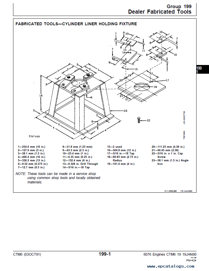
- Group 199—Dealer Fabricated Tools
- Fabricated Tools—Cylinder Liner Holding Fixture
- Index
In today's world of internal combustion engines are commonly used in almost all spheres of human activity. This industry and agriculture, all kinds of construction and repair work, transport services and much, much more.
Diesel engine, a number of technical features, more common in the construction, maintenance, and other special technique where the machine requires high power and endurance. This rail transport: locomotives, diesel trains, Track Vehicles. Road transport: cars, buses, trucks, machinery (tractors, bulldozers, rollers, etc.). Also, diesel engines are used in shipbuilding.
The diesel engine is an internal combustion engine operating on the principle of ignition of fuel in contact with the heated compressed air.
Our company provides for sale original spare part catalogs, workshop manuals, diagnostic software for all models of engines, cars, trucks, buses, forklifts, tractors, harvesters, cranes, buldozers, generators, construction and agricultural machines, motorcycles. To purchase a catalog online, please add the product to your cart, fill in the contact form online. Our managers proceed your order the same day.


![spare parts catalog CLAAS Parts Doc Offline Update v919 [02.2026]](/imgs/type_zapch.gif)

![repair manual John Deere Service Advisor AG & CF 5.4.44 [06.2025] Technical manuals & Diagnostic Software](/imgs/type_instr.gif)
![repair manual John Deere Service Advisor AG & CF 5.4.44 [06.2025] Technical manuals & Diagnostic Software](https://www.epcatalogs.com/file/base/7wCEvBLSdZwzQlQnrx3OWQi2kgNbbgYop7dTciHgkkCE6obhMi6hyZvEHYYAJhCiXMXG9VpCxA==/john-deere-service-advisor-ag-cf-5-3-225-05-2024.webp)


