This manual provides instructions for troubleshooting and repairing of Cummins engines B3.9 and B5.9 series.
This manual is organized to guide a service technician through the logical steps of identifying and correcting problems related to the engine.
Troubleshooting and repair manual includes step by step instructions, detailed pictures, and diagrams, technical specifications, etc.
Manual is a system of care in troubleshooting and repair of Cummins engines, which allows you to identify and resolve problems and inaccuracies.
Troubleshooting and repair manual is a file PDF, which contains 928 pages, any one of which we can be printed easily. We recommend using Adobe PDF Reader, to be sure all images/graphics will display correctly.
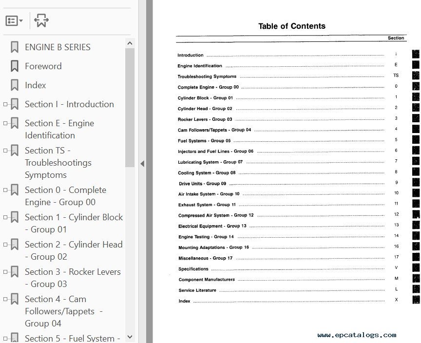
Contents:
- Section i - Introduction
- About the Manual
- Acronyms and Abbreviations
- General Cleaning Instructions
- General Safety Instructions
- How To Use the Manual
- Illustrations
- Symbols
- Section E - Engine Identification
- Engine Diagrams
- Engine Identification
- Specifications
- Section TS - Troubleshooting Symptoms
- Troubleshooting Procedures and Techniques
- Troubleshooting Symptoms Charts
- Section 0 - Group 00 - Complete Engine
- Complete Engine - General Information
- Engine Installation
- Engine Painting
- Engine Removal
- Service Tools
- Section 1 - Group 01 - Cylinder Block
- Bearings, Connecting Rod
- Bearings, Main
- Camshaft
- Camshaft Bushings
- Camshaft Gear (Camshaft Removed)
- Connecting Rod
- Crankshaft
- Crankshaft Gear
- Crankshaft Seal, Front
- Crankshaft Seal, Rear
- Crankshaft Wear Sleeve, Front
- Crankshaft Wear Sleeve, Rear
- Cylinder Block
- Engine Data plate
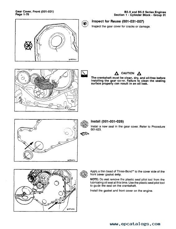
- Gear Cover, Front
- Gear Housing, Front
- Piston
- Piston and Connecting Rod Assembly
- Piston Rings
- Service Tools
- Timing Pin Housing
- Vibration Damper
- Section 2 - Group 02 - Cylinder Head
- Cylinder Head
- Cylinder Head - General Information
- Cylinder Head Gasket
- Injector Protrusion
- Service Tools
- Valve, Cylinder Head
- Valve Guide Seal, Cylinder Head
- Section 3 - Group 03 - Rocker Levers
- Crankcase Breather Tube
- Overhead Set
- Rocker Lever
- Rocker Lever Cover
- Service Tools
- Section 4 - Group 04 - Cam Followers / Tappets
- Cam Followers / Tappets - General Information
- Push Rods or Tubes
- Service Tools
- Tappet
- Section 5 - Group 05 - Fuel Systems
- AFC Assembly
- Cold Start Timing Advance System (KSB) Pump Mounted
- Cold Start Timing Advance System (KSB) Temperature Switch
- Engine Fuel Heater, Electric
- Flow Diagram, Fuel System
- Fuel Consumption
- Fuel Flow
- Fuel Injection Pump, In-Line, Spill Port Timing
- Fuel Injection Pump, Rotary
- Fuel Injection Pumps, In-Line
- Fuel Lift Pump
- Fuel Pump Back Leakage Valve
- Fuel Pump Control Lever and Spring
- Fuel Pump High Idle Speed
- Fuel Pump Pressure Regulator
- Fuel Pump Support Bracket
- Fuel Pump Timing
- Fuel Recommendations and Specifications
- Fuel Shutoff Valve
- Fuel System - General Information
- Service Tools
- Specifications
- Speed Droop Governor
- Section 6 - Group 06 - Injectors and Fuel Lines
- AFC Air Tube
- Air in Fuel
- Fuel Drain Line Restriction
- Fuel Filter (Spin-On Type)
- Fuel Inlet Restriction
- Fuel Manifold (Drain)
- Fuel Return Overflow Valve
- Fuel Supply Lines
- Fuel-Water Separator
- Injector
- Injector Supply Lines (High Pressure)
- Service Tools
- Section 7 - Group 07 - Lubricating System
- Engine Oil Heater
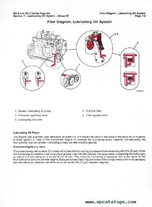
- Flow Diagram, Lubricating Oil System
- Lubricating Oil Contamination
- Lubricating Oil Cooler
- Lubricating Oil Dipstick
- Lubricating Oil Dipstick Tube
- Lubricating Oil Filter (Spin-On)
- Lubricating Oil Level
- Lubricating Oil Pan
- Lubricating Oil Pressure Regulator (Main Rifle)
- Lubricating Oil Pressure Sensor, OEM
- Lubricating Oil Pump
- Lubricating Oil Suction Tube (Block-Mounted)
- Lubricating Oil System - General Information
- Lubricating Oil System Diagnostics
- Service Tools
- Specifications
- Section 8 - Group 08 - Cooling System
- Coolant Heater
- Coolant Temperature Sensor, OEM
- Coolant Thermostat
- Coolant Thermostat Housing
- Cooling System
- Cooling System - Air or Combustion Gas Test
- Cooling System - General Information
- Cooling System Diagnostics
- Drive Belt, Cooling Fan
- Fan Belt Tensioner
- Fan Clutch, Electric
- Fan, Cooling
- Fan Hub, Belt Driven
- Fan Spacer and Pulley
- Flow Diagram, Cooling System
- Radiator
- Radiator Hoses
- Radiator Pressure Cap
- Radiator Shutter Assembly
- Sea Water Heat Exchanger
- Sea Water Pump
- Service Tools
- Specifications
- Water Pump
- Section 9 - Group 09 - Drive Units
- Hydraulic Pump Drive
- Hydraulic Pump Drive Gear and Shaft
- Section 10 - Group 10 - Air Intake System
- Aftercooler
- Air Crossover
- Air Intake Manifold
- Air Intake Manifold Heater
- Air Intake Restriction
- Air Intake System - General Information
- Air Leaks, Air Intake and Exhaust Systems
- Charge-Air Cooler (CAC)
- Flow Diagram, Air Intake System
- Service Tools
- Specifications
- Turbocharger
- Turbocharger Axial Clearance
- Turbocharger Blade Damage
- Turbocharger Compressor Seal Leaks
- Turbocharger Oil Drain Line
- Section 11 - Group 11 - Exhaust System
- Exhaust Manifold, Dry
- Exhaust Restriction
- Flow Diagram, Exhaust System
- Service Tools
- Specifications
- Section 12 - Group 12 - Compressed Air System
- Air Compressor Carbon Buildup
- Air Compressor Coolant Lines
- Air Compressor Cylinder Head
- Air Compressor Pin Bore Wear
- Air Compressor Unloader and Valve Assembly
- Air Governor
- Air Leaks, Compressed Air System
- Compressed Air System - General Information
- Flow Diagram, Compressed Air System
- Service Tools
- Specifications
- Section 13 - Group 13 - Electrical Equipment
- Alternator
- Alternator Bracket
- Alternator Pulley
- Batteries
- Battery Cables and Connections
- Electrical Equipment - General Information
- Electronic Wiring Diagram
- Service Tools
- Specifications
- Starter Magnetic Switch
- Starter Solenoid
- Starter Switch
- Starting Motor
- Section 14 - Group 14 - Engine Testing
- Crankcase Blowby, Measure
- Engine Run-in
- Engine Testing
- Service Tools
- Specifications
- Section 16 - Group 16 - Mounting Adaptations
- Engine Mounts
- Engine Support Bracket, Front
- Engine Support Bracket, Rear
- Flywheel
- Flywheel Housing
- Flywheel Ring Gear
- Service Tools
- Section 17 - Group 17 - Miscellaneous
- Cup Plug
- Expansion Plug
- Pipe Plug
- Service Tools
- Section V - Specifications
- Air Intake System
- Cam Followers/Tappets
- Capscrew System - Specifications
- Compressed Air System
- Cooling System
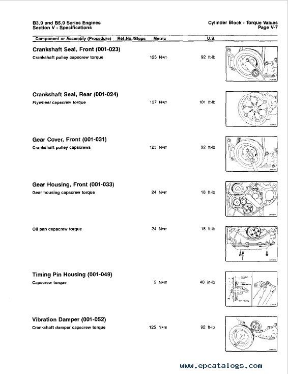
- Cylinder Block
- Cylinder Head
- Drive Belt Tension
- Electrical Equipment
- Engine Component Torque Values
- Engine Testing
- Exhaust System
- Fraction, Decimal, Millimeter Conversions
- Fuel System
- Injectors and Fuel Lines
- Lubricating Oil System
- Mounting Adaptations
- Newton-Meter to Foot-Pound Conversion Chart
- Pipe Plug Torque Values
- Rocker Levers
- Specifications
- Tap-Drill Chart
- Weights and Measures
- Section M - Component Manufactures
- Component Manufacturer's Addresses
- Section L - Service Literature
- Additional Service Literature
- Service Literature Ordering Location
- Index
Our company provides for sale original spare part catalogs, workshop manuals, diagnostic software for all models of engines, cars, trucks, buses, forklifts, tractors, harvesters, cranes, buldozers, generators, construction and agricultural machines, motorcycles. To purchase a catalog online, please add the product to your cart, fill in the contact form online. Our managers proceed your order the same day.


![spare parts catalog CLAAS Parts Doc Offline Update v919 [02.2026]](/imgs/type_zapch.gif)


